Allen-Bradley Bulletin 2705 RediPANEL Keypad Modules (Cat. Nos.
Important User Information Solid state equipment has operational characteristics differing from those of electromechanical equipment. “Safety Guidelines for the Application, Installation and Maintenance of Solid State Controls” (Publication SGI-1.1) describes some important differences between solid state equipment and hard–wired electromechanical devices.
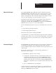
Table of Contents RediPANEL Keypad Modules A–BUser Manual Using this Manual Chapter 1 Chapter Objectives . . . . . . . . . . . . . . . . . . . . . . . . . . . . . . . . . . . . . . . . . What this Manual Contains . . . . . . . . . . . . . . . . . . . . . . . . . . . . . . . . . . Audience . . . . . . . . . . . . . . . . . . . . . . . . . . . . . . . . . . . . . . . . . . . . . . . . Reference Materials . . . . . . . . . . . . . . . . . . . . . . . . . . . . . . . . . . . . . . . . Definition of Terms . .
Table of Contents RediPANEL Keypad Module User Manual Selecting Options Chapter 5 Chapter Objectives DIP Switches Typical Switch Settings Setting Switch Bank #1 Setting Switch Bank #2 Setting Switch Bank #3 Operating Modes Chapter 6 Chapter Objectives Keypad Output Display Numeric Data ASCII Data Display Stored Message ASCII Message Display Data Entry Split Display Decimal Modes Polarity Destination Entry Messages Keyboard Entering Messages Storing Editing Editing Commands Programming 6–1 6–1 6–2 6–2
Table of Contents RediPANEL Keypad Module User Manual Instruction Parameters Programming Example Programming Example PLC–2 Programming Example PLC–2 Example Program Program Set–up Part A: Changing and Examining Accumulated Value of Counter for PLC–2 Part B: Changing and Examining Preset Value of Counter for PLC–2 Part C: Displaying a 16–Character Message for PLC–2 Part D: Displaying Message and Variable Data Simultaneously for PLC–2 Part E: Using Destination Bits to Retrieve or Change Data for PLC–2 Symbol
Chapter 1 Using this Manual Chapter Objectives This chapter describes the manual’s organization, intended audience, and special terminology. What this Manual Contains This manual describes the equipment, communication protocol, command structure, installation, operation, troubleshooting, and specifications for the Allen–Bradley Bulletin 2705 RediPANEL Keypad Modules (Catalog Numbers: 2705–K11C1, –K11C2, –K12C2, –K12C3, –K12C4).
Chapter 1 Using this Manual Audience To get maximum benefit from this manual and the best use of the Bulletin 2705 Keypad Module in your system, you must be able to operate and program an Allen–Bradley Programmable Logic Controller (PLC) or Small Logic Controller (SLC). Reference Materials We make reference in this manual to several other publications. They are: • • • • Definition of Major Terms Allen–Bradley Publication 1770–4.1 (for grounding and wiring guidelines).
Chapter A–B 2 Product Introduction Chapter Objectives This chapter describes the features, functions and operation of the Bulletin 2705 RediPANEL Keypad Module. Features The Bulletin 2705 RediPANEL Keypad Module is an operator module that connects directly to an Allen–Bradley PLC via the remote I/O link. It provides the capability for operators to input data to and retrieve data from the PLC. It also functions as a single line message display.
Chapter 2 Product Introduction Applications The Keypad Module combines the functions of standard thumbwheel or push button devices with the built–in capabilities of a remote I/O rack. The Keypad Module communicates directly with the programmable controller via the Remote I/O link. You can install a 2705 module anywhere along that link. To the PLC, the Keypad Module looks like a hardwired remote I/O rack. The function keys and the LED output signals are programmed as discrete I/O in the PLC.
Chapter 2 Product Introduction Operator Data Input The 2705 RediPANEL Keypad Module features a numeric keypad with DELETE, ENTER, decimal and polarity keys. Using the keypad, operators can enter up to eight (8) digits (seven digits for signed numbers), which appear on the right side of the 16 character display. If an attempt is made to enter more than eight digits, only the first eight are accepted.
Chapter 2 Product Introduction 2) A combination of ASCII and numeric data. Up to 8 characters of ASCII data are displayed on the left side of the display and 8 digits of numeric data are displayed on the right side of the display. This allows you to label numeric data with text. The ASCII data can consist of either the first 8 characters of a stored message or 8 characters sent from the PLC controller.
Chapter A–B 3 Installing the Bulletin 2705 Keypad Module Chapter Objectives This chapter lists electrical precautions and power and grounding requirements for installing the Bulletin 2705 RediPANEL Keypad Module. Topics also include selecting NEMA enclosures, the mechanical installation of the module, and connecting to remote I/O links and to scanner modules.
Chapter 3 Installing the Bulletin 2705 Keypad Module Grounding Grounding is an important safety measure in electrical installations. With solid state systems, as we mentioned before, grounding also helps to limit the effect of noise due to EMI (electromagnetic interference). An authoritative source on grounding requirements is the National Electrical Code published by the National Fire Protection Association of Boston, Massachusetts.
Chapter 3 Installing the Bulletin 2705 Keypad Module Figure 3.1 shows recommended spacing for modules inside the NEMA enclosure. Figure 3.1 Spacing for Modules inside the NEMA Enclosure B A B B Recommended spacing: A A= 6“ (15cm) from lower edge of top cutout to upper edge of lower cutout B= 1“ (2.5cm) from outside edge of mounting flange B Mechanical Installation Depth of enclosure = 8“ (20cm) or more. Mounting tabs are built into the module.
Chapter 3 Installing the Bulletin 2705 Keypad Module To install the module, follow these guidelines: Step 1 - Cut an opening in the panel approximately 5.86” (149mm) H x 8.61” (219mm) W. See Figure 3.3. Figure 3.3 Mounting Dimensions of the Module Step 2 - Drill six 0.312” (7.6mm) diameter holes for the top and bottom mounting brackets. A template is provided with the module to assist in this operation. Step 3 - Slide the module through the opening.
Chapter 3 Installing the Bulletin 2705 Keypad Module Step 4 - To complete the mechanical installation, apply the mounting brackets and tighten all the captive knurled thumbscrews to 5 in–lbs. only. A torque screwdriver is recommended for this operation. Figure 3.4 shows the location of these screws. Figure 3.4 Mounting Bracket Thumbscrews Connecting to a Remote I/O Link The remote I/O link begins at the scanner module.
Chapter 3 Installing the Bulletin 2705 Keypad Module Connecting a Scanner Module Connect the Keypad Module to the scanner module with Allen–Bradley I/O cable (Catalog No. 1770–CD) or Belden #9463. Refer to Publication 1770–4.1 for detailed grounding and wiring guidelines. The user’s manual or product data sheet for your scanner module will also provide cabling information.
Chapter A–B 4 Configuring the Bulletin 2705 Keypad Module with PLC Controllers Chapter Objectives This chapter lists compatibility considerations for operating the Bulletin 2705 RediPANEL Keypad Module with programmable controllers via the remote I/O link. Topics also include the remote I/O architecture and factors in calculating rack size. Communications Bulletin 2705 Keypad Modules communicate with all Allen–Bradley programmable controllers that support the remote I/O link.
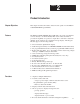
Chapter 4 Configuring the Bulletin 2705 Keypad Modules with PLC Controllers Remote I/O Architecture The following diagrams show applications using the Bulletin 2705 Keypad Module in systems using applicable PLC’s and scanners. Figure 4.1 Keypad Module with Mini–PLC (PLC–2/05, PLC–2/15, PLC–2/16, PLC–2/17) ËËËËË Keypad Mini–PLC–2 Scanner Module 1771–SN* ËËËËË Keypad * 1771 scanner module must be mounted in rack with the PLC. Figure 4.
Chapter 4 Configuring the Bulletin 2705 Keypad Module with PLC Controllers Remote I/O Architecture (continued) Figure 4.3 Keypad Module with PLC–3 ËËËËË ËËËËË Keypad PLC–3 Scanner Module 1775–S4A or 1775–S5 or 1775–S4B ËËËËË ËËËËË Keypad Figure 4.
Chapter 4 Configuring the Bulletin 2705 Keypad Modules with PLC Controllers Figure 4.5 Keypad Module with PLC–5/15, 5/25 ËËËËË Keypad PLC–5/15 PLC–5/25 Scanner Port 1785 ËËËËË Keypad Figure 4.
Chapter 4 Configuring the Bulletin 2705 Keypad Module with PLC Controllers Figure 4.7 Keypad Module with SLC–5/02 ËËËËË ËËËËË Keypad SLC–5/02 RIO Scanner Port 1747–SN Compatible PLC Controllers and Scanners ËËËËË Keypad The Bulletin 2705 Keypad Module is compatible with all Allen–Bradley scanners that support remote I/O. Tables 4.A, 4.B and 4.C on this and the following page list applicable PLC’s and scanners.
Chapter 4 Configuring the Bulletin 2705 Keypad Modules with PLC Controllers Table 4.B Applicable Programmable Controllers Requiring 1771-SN Sub-scanner* Catalog Number Description Related Pub. No. 1772–LS, LSP Mini–PLC–2/05 1772–6.8.6 1772–LV Mini–PLC–2/15 1772–6.8.2 1772–LX, LXP Mini–PLC–2/16 1772–2.26 1772–LW, LWP Mini–PLC–2/17 1772–2.25 1772–LN Mini–PLC–2 1772–6.8.4 1785–LT3 PLC–5/12 1785–6.8.2 * The 1771–SN sub I/O scanner can be used with any PLC-2 or PLC-5 family processor.
Chapter 4 Configuring the Bulletin 2705 Keypad Module with PLC Controllers Calculating Rack Size The 2705 Keypad Module can be configured for any of four rack sizes: 1/4, 1/ , 3/ , and a full rack. Rack sizes relate to the amount of I/O accessible to 2 4 each rack: 32 I/O bits or points for 1/4 rack, 64 for 1/2 rack, 96 for 3/4 rack and 128 for a full rack. You set DIP switches for the rack size you want in your system design. See Chapter 5 on DIP switch settings.
Chapter 4 Configuring the Bulletin 2705 Keypad Modules with PLC Controllers Remote I/O Configuration Once you have selected the appropriate scanner for the PLC controller, Table 4.E below lists how many separate chassis the scanner can support and how much I/O it can address.
Chapter A–B 5 Selecting Options Chapter Objectives This chapter describes DIP switch location and functions on the Bulletin 2705 RediPANEL Keypad Module. It also lists the switch bank settings for selecting function and configuration options. DIP Switches See Figure 5.1 to identify the Keypad Module switch banks. Figure 5.1 Switch Bank Location and Functions on Bulletin 2705 Keypad Module Switch bank #1 (SW–1) sets the rack address.
Chapter 5 Selecting Options Typical Switch Settings The following figures show examples of DIP switch settings. Figure 5.2 illustrates the “ON” and “OFF” positions of the DIP switches. Figure 5.2 Setting DIP Switches Setting Switch Bank #1 Figure 5.3 gives functions and settings for Switch Bank #1. Notice that the rack address settings apply only to PLC–2 or any other PLC usung a 1771–SN Sub I/O Scanner Module. Rack address settings for PLC–3, PLC–5/15 and PLC–5/25 are listed in Figure 5.
Chapter 5 Selecting Options Figure 5.4 lists the rack address settings on Switch Bank #1 for PLC–3, PLC–5/15, PLC–5/25 and SLC–5/02 controllers. Figure 5.4 Setting Switch Bank #1 for PLC–3, PLC–5/15, PLC–5/25 and SLC–5/02.
Chapter 5 Selecting Options Setting Switch Bank #2 FigureFigure 5.5 5.5 gives the switch functions and settings for switch bank #2. Setting Switch Bank #2 Figure 5.5 Setting Switch Bank #2 BAUD RATE 57.6K 1–ON 115.2K 1–OFF 230.4K 1–ON N/A 1–OFF OFF ON Example – PLC–5/15 1 2 3 4 5 6 7 8 OFF ON Baud Rate 57.
Chapter 5 Selecting Options Setting Switch Bank #3 Figure 5.6 gives the switch functions and settings for Switch Bank #3. These Figure 5.5 switch bank #3 settings are for all PLC’s. Setting Switch Bank #2 Figure 5.
Chapter A–B 6 Operating Modes Chapter Objectives This chapter describes the operating modes of the Bulletin 2705 RediPANEL Keypad Module. Topics include: • Keypad Output Display PLC output display of numeric and ASCII data and 16–character messages • Data entry, decimal modes, split display data entry • Message entering, storing and editing • Destination entry The Keypad Module’s vacuum fluorescent display shows 16 alphanumeric characters. Figure 6.1 shows the features of the display.
Chapter 6 Operating Modes Numeric Data Numeric data appears on the right–hand side of the display in the eight right–most character positions. These positions display eight digits (seven for negative numbers). The decimal point, if used, does not require an additional character position. ASCII Data Text starts on the left–most element. Text is displayed left to right. Display Stored Message A maximum of 16 ASCII characters can be displayed when using a stored message.
Chapter 6 Operating Modes Data Entry The Keypad Module offers a standard numeric keypad interface with a polarity (minus sign) key and a decimal point as shown in Figure 6.2. Additional features are DELETE and ENTER keys, and six programmable function keys with LED’s. Figure 6.2 Keypad Layout COMM 7 8 9 F1 F2 4 5 6 F3 F4 1 2 3 F5 F6 - 0 . ENTER FAULT DELETE The Keypad Module accepts up to eight digits of data.
Chapter 6 Operating Modes To enter data you must first key in the desired numbers using the numeric keypad. The data will appear on the right hand side of the display as the numbers are being keyed. To complete data entry you must press the ENTER key. The entered data is placed directly into the data word(s) of the Input Image table. Any ASCII characters in the left hand side of the display remain there during data entry, unless the Split Display feature is enabled.
Chapter 6 Operating Modes . Figure 6.3 Display for Destination Entry The keypad operator starts by pressing the ENTER key. The present destination is displayed between the >>––––>> symbols as shown in Figure 6.3. The flashing >> symbol prompts the operator for a new destination number, followed by another ENTER keystroke. After the second ENTER, the new destination is mapped directly into the destination word.
Chapter 6 Operating Modes The Message Editor inside the module is accessed by the keyboard when any key is depressed. A prompt appears on the display to begin the editing process. The Message Editor contains commands to create, edit and save single line, 16–character alphanumeric messages. Each message is assigned a message number for reference by the PLC or for future editing. Figure 6.4 Keyboard Plug Receptacle Figure 6.
Chapter 6 Operating Modes Entering Messages The procedure for entering messages into the module is interactive: Step 1 - Remove power before plugging keyboard into the module. Step 2 - Depress any key to enter the edit mode. Step 3 - The module asks you for a message number: Step 4 - Type a message number (1 to 120) and depress ENTER or depress ENTER to edit message number displayed. Step 5 - If the number you entered has a message assigned to it, the module displays that message for you to edit.
Chapter 6 Operating Modes Editing Commands The editing commands are single key strokes: Left arrow (←) - Move cursor one position to the left. Right arrow(→) - Move cursor one position to the right. Down arrow(↓) - Decrement number of message to be created or edited. Up arrow(↑) - Increment number of message to be created or edited. Control–B - Set message FLASH attribute. Control–D - Delete message and return to run mode. Control–F - Display number of free messages.
Chapter A–B 7 Programming Chapter Objectives This chapter describes the process of creating a program for the Bulletin 2705 RediPANEL Keypad module. The detailed listing of the program example explains the ladder logic programming. Introduction Of Programming with the Keypad Module Applications for the Keypad Module are programmed in the Allen–Bradley PLC controller. The module itself has an on–board message editor that can create and store up to 120 single line messages.
Chapter 7 Programming PLC-5 Programming Examples The PLC–5 programming examples given on the following pages are based on the system configuration listed below. System Configuration Note – System configuration may vary for different applications. 1. A 1784–T45 Portable Terminal 2. A 1785–LT PLC–5/15 Processor (Ser. B Rev. H, Set for Scanner Mode) 3. A 1771–P4 Power Supply 4. A 1771–A1B 4 slot chassis 5. A 2705–K11C1 RediPANEL Keypad Module (Ser. B Rev.
Chapter 7 Programming Input and Output Image Tables Figure 7.1 below shows the Input and Output Image Tables for the system configuration described on Page 2. Figure 7.1 Integer Mode, 1/2 Rack with Stored Message Display INPUT RACK # MODULE GROUP (WORD) I: 02 0 Integer Data I: 02 1 Destination I: 02 2 Destination Bits I: 02 3 Input Image Table Bits 17 16 15 14 13 12 11 10 7 H EN F6 F5 F4 F3 F2 F1 – 6 5 4 Dec. Pos.
Chapter 7 Programming Displaying Numeric Data Figure 7.2 Rung 2:0 F1 Function Key I:020 ] [ 10 CTU COUNT UP Counter Preset Accum C5:1 69 50 (CU) (DN) Rung 2:1 F1 Function Key I:020 ] [ 10 MOV MOV Source Dest C5:1.ACC 50 0:021 69 The program example in Figure 7.2 illustrates how the function key, F1, may be used just like a push button or other similar input type device. In this instance, F1 is used to increment the accumulative value of count up counter C5:1 and initiate a MOVE instruction.
Chapter 7 Programming Triggering a Stored Message to Describe Data The Keypad Module is not only capable of displaying numeric data, but also alphanumeric messages to describe that data. These messages may be stored in the programmable controller and sent to the Keypad Module via ASCII code, or store up to 120 messages in the Keypad Module and trigger them according to their message number. The later method is the most common means of displaying messages on the Keypad Module.
Chapter 7 Programming Rung 2:2 shows how the same input, F1, which is used to move the accumulated value of the counter to the Keypad display, can also trigger a stored message. The MOVE instruction in rung 2:2, moves the constant 1 to 0:022, the word in the output image table where the Stored Message Display (SMD) number is sent to the Keypad Module. (See Figure 7.1, Input and Output Image Tables.) In this case when F1 is pressed, message number 1 ”C5.1 ACC.
Chapter 7 Programming In Figure 7.4, function key F3 is used to initiate a MOVE instruction. The MOVE instruction, moves the constant 3 to the Keypad module’s stored message word 0:022. This in turn triggers stored message number 3 “16 CHARACTER MSG.”. The second rung in Figure 7.4, Rung 2:4 uses a Greater Than/Equal To instruction (GEQ) to control the DM bit.
Chapter 7 Programming Figure 7.5 Rung 2:5 Enter Key I:020 ] [ MOV MOV Source 16 Dest Rung 2:6 F2 Function Key I:020 ] [ 11 MOV MOV Source Dest Enter Key I:020 ] [ 16 I:021 50 C5:1.PRE 69 2 0:022 2 MOV MOV Source Dest C5:1.PRE 69 0:021 69 In the example shown in Figure 7.5, rung 2:5 is used to move the value from the input image table, I:021, to counter C5.1 preset, each time the Enter key is pressed. Rung 2:6 in Figure 7.
Chapter 7 Programming Using the Destination Function to Load Multiple Timer Presets The keypad destination function can be used to load data values into multiple timer/counter presets or other PLC memory locations. The example program listed below can be used to load preset values into 17 consecutive timer presets, beginning with T4:0.PRE and ending with T4:16.PRE. Rungs 3 through 16 have been omitted to simplify the example.
Chapter 7 Programming Rungs 3–16: Would appear the same but with different timer/destination bit addresses. Rung 17: Destination bit I:024/00 is “ON” when the keypad operator enters destination number “17”. All other destination bits are “OFF”. The ENTER bit I:020/16 prevents data from being moved until the keypad operator enters a new preset for T4:16. The MOVE instruction takes the integer data in I:021 and transfers it to T4:16.PRE.
Chapter 7 Programming Using PLC-5 Controllers and a Sub I/O Scanner with Keypad Modules A 1771–SN, Sub I/O scanner may be used with a PLC–5 family processor when the application requires more remote devices than that processor can accommodate. The sub I/O scanner module may be used to communicate to as many as 16 additional remote I/O devices. The 1771–SN Sub I/O scanner may be located in the same rack as the PLC–5 (the local rack), or in any space of the remote racks supported by the processor.
Chapter 7 Programming The ladder diagram in Figure 7.6 is a simple programming example showing Bidirectional Block Transfers between a sub I/O scanner and PLC–5. Figure 7.6 PLC–5 Block Transfer BTR Enable Bit N10:0 ]/[ 15 BTW Enable Bit N10:5 ]/[ 15 BTR BTW Enable Bit Enable Bit N10:0 ]/[ 15 N10:5 ]/[ 15 Read from Sub–Scanner to the PLC–5.
Chapter 7 Programming be reflected in this file. Therefore, all your input or output addresses for these remote devices will be elements of this file. • LENGTH is the number of words the sub I/O scanner is transferring. The number entered will be equal to 8 words (reserved for sub I/O scanner utility functions) plus 2 words for each 1/4 rack of I/O the sub I/O scanner will be communicating with.
Chapter 7 Programming Figure 7.
Chapter 7 Programming In the programming example shown in Figure 7.7, you’ll notice the length has been set for (12), 8 words for the block transfer utility functions and 4 words for the Keypad Modules configured for 1/2 rack. The DATA FILE for the block transfer read instruction begins at N11:0. This means the addresses in the ladder logic, for the keypad input, will begin with N11:8/00. The DATA FILE for the block transfer write instruction begins at N12:0.
Chapter 7 Programming PLC-2 Programming Example The following pages contain a PLC–2 example program which utilizes many of the functions of the Keypad Module. Keep in mind that this program is simply an example - your applications may or may not fit this structure.
Chapter 7 Programming PLC–2 Programming Example The example program below is explained on the following pages. We present the program here (and on the next page) in its entirety for your reference. Note – Block transfer is only required when using the 1771–SN sub I/Oscanner Block transfers allow communications between the sub–scanner and PLC. Block transfers are not required for any other type of scanner module.
Chapter 7 Programming 540 310 7 ( + ! ! 8 + ! ! 9 + ! ! 0137 540 540 11 ! ! + ! ! 12 310 ! ! 15 + ! ! 16 + ! ! ( PUT ) + 003 0137 ! ! 0312 G ( PUT ) + 0412 ! ! ( PUT ) + 16 000 0137 310 G 16 500 540 310 214 540 ( 00 16 310 511 G 13 + ! ! 14 + 0413 ! ! 002 + ! ! + 214 003 0515 10 + 00 ( CTU ) 500 G 00 15 U ) 00 0413 + 410 310 ( L 410 310 ( U G 14 ! ! + 0413 + 0412 ! ! ( PUT ) + 214 00 END 01107 The explanation of the example program begi
Chapter 7 Programming Program Set-up ! A + ! ! ! ! ! + B ! ! ! ! ! ! C + ! ! ! ! ! ! ! Rungs A, B and C set the program up: + + + + + + + 111 + + 17 BLOCK XFER READ DATA ADDR: 0030 MODULE ADDR: 111 BLOCK LENGTH 14 FILE: 0200–0215 + + + 111 + (DN) + 011 (EN) 16 + (DN) 16 + + 0033 (EN) 17 BLOCK XFER WRITE + DATA ADDR: 0031 MODULE ADDR: 111 BLOCK LENGTH 14 FILE: 0400–0415 FILE TO FILE MOVE COUNTER ADDR: 0031 POSITION: 014 FILE LENGTH 014 FILE A: 17 111 0033 (DN) 0200–0215
Chapter 7 Programming Figure 7.9 I/O Table for Sample Program: BCD Mode, 3/4 Rack Input Image Table 17 16 15 14 13 12 11 10 7 H EN F6 F5 F4 F3 F2 F1 S 6 5 4 Dec. Pos. 3 – 2 – 1 – 0 – Word 310 BCD1 (MSD) BCD2 BCD3 BCD4 Word 311 BCD5 BCD6 BCD7 BCD8 (LSD) Word 312 Destination Word 313 Destination Bits Word 314 Destination Bits Word 315 Output Image Table 17 H 15 14 13 12 11 10 7 DMM L6 L5 L4 L3 L2 L1 S 16 6 5 4 Dec. Pos.
Chapter 7 Programming Part A: Changing and Examining Accumulated Value of Counter for PLC-2 1 2 3 4 5 ! + 310 ! ! + 10 ! ! + ! ! + ! ! + ! ! ! Rungs 1–5 show a procedure for monitoring the accumulated value of counter 037 using the Keypad Module: 0037 ( CTU ) PR 500 AC 214 0037 0500 ( PUT ) G 063 063 477 500 ( CTU ) 15 00 477 500 ( 00 310 0500 0412 ( PUT ) G 10 ) 17 063 063 ! ! ! ! ! ! ! ! ! ! ! ! ! ! ! ! Rung 1: The input signal, function key F1, is programmed to increment
Chapter 7 Programming Part B: Changing and Examining Rungs 7–12 show a programming procedure that will allow you to change the preset values of the counter that was being monitored in rungs 1–5. preset Value of Counter for (Rung 6 and Rung 9 are for message recording, and will be explained later).
Chapter 7 Programming Part C: Displaying a 16–Character Message for PLC–2 310 0413 0511 G 13 + 15 ! ! 14 + ! Rungs 13 - 17 retrieve and display a message: + ( PUT ) 001 001 ! ! 410 310 ( 15 ) + 16 ! L Rung 13: When function key F6 is depressed, a number is retrieved from word 511 and put in the output image table location (413) reserved for a stored message number. (Refer to output image table.) Shown above - message number “1” is being moved to word 413.
Chapter 7 Programming Part D: Displaying Message and In Part A and B we learned how to examine information from the PLC by Variable Data Simultaneously for using the Keypad. In order to have an 8–character message work with the variable data a message number must be put into the stored message word of PLC-2 the output image table at the same time the variables appear on the keypad display.
Chapter 7 Programming Symbols and Abbreviations for I/O Image Tables The figures on the following pages show the input and output tables for the Keypad Module. The following symbols and abbreviations appear in the input and output tables. Refer to this list for identifying specific bits in the tables: “-” Represents a “0”. No function is assigned for this bit location. H Handshake bit. Refer to page 7–28 for more information. EN ENter bit.
Chapter 7 Programming Decimal Point Control Dec. Pos. DECimal POSition. The decimal position field holds a binary value (1–7) that is the number of positions to the right of the decimal point: Input Image table – Indicates the number of places to the right of the decimal point as numeric data is being entered. Output Image table – Controls the number of places to the right of the decimal point when the Keypad Module is displaying variable data. DC Decimal point Control. Decimal point control enables SDP.
Chapter 7 Programming Figure 7.10 Example of Decimal Point Control Input Image Table - Integer Mode 17 H 16 EN 15 F6 14 F5 13 F4 12 F3 11 F2 10 F1 7 – 6 0 5 0 4 1 3 2 1 0 – – – – 3 2 1 0 Word 0 Output Image Table - Integer Mode 17 16 15 14 13 12 11 10 7 6 H DM L6 L5 L4 L3 L2 L1 – 0 5 1 4 1 1 0 Dec. Pos.
Chapter 7 Programming When to Use the Handshake Mode RediPANEL Modules have a standard TIMED feature that holds all push button depressions for a minimum of 100 milliseconds to allow the PLC controller to read the depression during its scan cycle. No special programming is needed for this function. Most system configurations can use this feature to help insure data capture of a push button depression. As a general guideline, handshaking is not required. The few cases where it is required would be: 1.
Chapter 7 Programming With the handshake feature enabled and the handshake rung in the user’s program, the RediPANEL module holds all function key input signals high for a minimum of one complete PLC program scan. It keeps the signal(s) high for one complete cycle of the handshake input bit. The handshake input and output signals will continuously toggle independent of any function key closures. This ensures that the handshake function is operational even if no function keys have been pressed.
Chapter 7 Programming Input and Output Image Tables Integer Data – With Stored Message 1/ , 3/ and Full Rack 2 4 Figure 7.13 Integer Mode, 1/2, 3/4 and Full Rack with Stored Message Display Input Image Table - Integer Mode 17 16 15 14 13 12 11 10 7 H EN F6 F5 F4 F3 F2 F1 – 6 5 4 Dec. Pos.
Chapter 7 Programming Input and Output Image Tables BCD Data – With Stored Message 3/ and Full Rack 4 Figure 7.14 BCD Mode, 3/4 and Full Rack with Stored Message Display Input Image Table - BCD Mode 17 16 15 14 13 12 11 10 7 H EN F6 F5 F4 F3 F2 F1 S 6 5 4 Dec. Pos.
Chapter 7 Programming Input and Output Image Tables Binary Data – With Stored Message 1/ , 3/ and Full Rack 2 4 Figure 7.15 Binary Mode, 1/2, 3/4 and Full Rack with Stored Message Display Input Image Table - Binary Mode 17 16 15 14 13 12 11 10 7 H EN F6 F5 F4 F3 F2 F1 S 6 5 4 Dec. Pos.
Chapter 7 Programming Input and Output Image Tables Integer Data – With Stored Message 1/ , 3/ and Full Rack 2 4 Figure 7.16 Integer Mode, 1/2, 3/4 and Full Rack Input Image Table - Integer Mode 17 16 15 14 13 12 11 10 7 H EN F6 F5 F4 F3 F2 F1 – 6 5 4 Dec. Pos.
Chapter 7 Programming Input and Output Image Tables Integer Data – With Stored Message 1/ Rack 4 Figure 7.17 Integer Mode, 1/4 Rack 17 Input Image Table 17 16 15 14 13 12 11 10 7 H EN F6 F5 F4 F3 F2 F1 S 6 5 4 3 Dec. Pos. 2 1 0 Destination Word 0 Integer Data Word 1 Output Image Table 17 16 15 14 13 12 11 10 7 H DM L6 L5 L4 L3 L2 L1 S Integer Data 7–34 6 5 Dec. Pos.
Chapter 7 Programming Input and Output Image Tables Binary Data – With Stored Message 3/ and Full Rack 4 Figure 7.18 BCD Mode, 3/4 and Full Rack Input Image Table - BCD Mode 17 16 15 14 13 12 11 10 7 H EN F6 F5 F4 F3 F2 F1 S 6 5 4 Dec. Pos.
Chapter 7 Programming Input and Output Image Tables Binary Data – With Stored Message 1/ Rack 4 Figure 7.19 BCD Mode, 1/4 Rack Input Image Table 17 16 15 14 13 12 11 10 H EN F6 F5 F4 F3 F2 F1 BCD3 7 BCD4 6 5 4 3 2 1 0 BCD1 (MSD) BCD2 Word 0 BCD5 BCD6 (LSD) Word 1 Output Image Table 17 16 15 14 13 12 11 10 H DM L6 L5 L4 L3 L2 L1 BCD3 7 BCD4 6 5 4 3 2 1 0 BCD1 (MSD) BCD2 Word 0 BCD5 BCD6 (LSD) Word 1 1/ Rack 2 Figure 7.
Chapter 7 Programming Input and Output Image Tables Binary Data – No Stored Message 1/ , 3/ and Full Rack 2 4 Figure 7.21 Binary Mode, 1/2, 3/4 and Full Rack Input Image Table - Binary Mode 17 16 15 14 13 12 11 10 7 H EN F6 F5 F4 F3 F2 F1 S 6 5 4 Dec. Pos.
Chapter 7 Programming Input and Output Image Tables Binary Data – No Stored Message 1/ Rack 4 Figure 7.22 Binary Mode, 1/4 Rack Input Image Table 17 16 15 14 13 12 11 10 7 H EN F6 F5 F4 F3 F2 F1 S 6 5 4 3 Dec. Pos. 2 1 0 Destination Word 0 Binary Data Word 1 Output Image Table 17 16 15 14 13 12 11 10 7 H DM L6 L5 L4 L3 L2 L1 S Binary Data 7–38 6 5 4 Dec. Pos.
Chapter 7 Programming SLC–5/02 Programming Example In the following example, a Bulletin 2705 RediPANEL displays stored messages. An alarm, connected to an output module, signals when communications with the RediPANEL are lost. The system consists of: • SLC–5/02 Processor (Catalog No. 1747–L524) in slot 0 • Remote I/O Scanner (Catalog No. 1747–SN) in slot 1 • Output Module (Catalog No.
Chapter 7 Programming The scanner input file is shown below. The output file is similar, it is addressed O:1.0 to O:1.3. Bit Number Ra 0 Rack Ra 1 Rack Ra 2 Rack Ra 3 Rack 14 13 12 11 10 9 8 7 6 5 4 3 2 1 0 Input File Rack 0 Group 0 Word 1 I:1.0 Rack 0 Group 1 Word 1 I:1.1 Rack 0 Group 2 Word 2 I:1.2 Rack 0 Group 3 Word 3 I:1.3 Rack 0 Group 4 Word 4 not used I:1.4 Rack 0 Group 5 Word 5 not used I:1.5 Rack 0 Group 6 Word 6 not used I:1.
Chapter 7 Programming Address Conversion The addresses for the Input and Output files are provided in an octal format. You must convert the bit addresses to decimal to accommodate the SLC–5/02. Refer to the following. Bit Address Scanner Configuration Decimal 1 2 3 4 5 6 7 8 9 10 11 12 13 14 15 SLC–5/02 Octal 1 2 3 4 5 6 7 10 11 12 13 14 15 16 17 PLC–5 The BAUD rate is 115.2K. DIP switch 1 should be in the OFF position, DIP switch 2 should be ON.
Chapter 7 Programming Example Program The example program is shown below. Each time a function key is pressed on the RediPANEL, its associated message is displayed. This program also monitors the scanner’s Enabled Device Fault bit (M1:1.0/0). If communications are lost, an alarm is activated. If the communications attempted and Enabled Device Fault bits are set to 1, activate the alarm. If function key 1 is pressed (bit 8 of input word 0), T4:0 preset is moved to the display.
Chapter A–B 8 Maintenance and Troubleshooting Chapter Objectives This chapter describes how to use the Comm/Fault LED indicators, and explains the power–up sequence error message display, plus addresses basic troubleshooting questions on the RediPANEL Keypad Module. Using the Comm/Fault LED Indicators Two LED indicators are located on the right top corner of the module a green LED labeled COMM and a red LED labeled FAULT.
Chapter 8 Maintenance and Troubleshooting The COMM Indicator Any communication faults or errors are indicated by the green LED labeled COMM. The LED can be in one of three states: 1. OFF 2. ON 3. Blinking COMM OFF When COMM indicator is OFF: 1. The module is not receiving input power. 2. The module is operating correctly, but no communications is occurring at this time. Check the Remote I/O Link wiring. 3. The module is the last rack, but the DIP switch indicating this state is not in the OFF position.
Chapter 8 Maintenance and Troubleshooting • • • Have you changed the settings of any of the DIP switches? New DIP switch settings will not be acknowledged until power is recycled. Refer to Chapter 5. If you do not have the communications LED ON and all of your DIP switches seem correct – check the remote I/O link wiring. You may need to reverse the blue and clear wires. If your 120 Volt AC is intermittent be sure your 120/240 Volt AC selectable switch is set properly.
Chapter A–B 9 Specifications Chapter Objectives This chapter lists the specifications for the Bulletin 2705 Keypad Module. Specifications FUNCTION Provides keypad interface for data entry and display in Remote I/O Serial Data Link. POWER AND ENVIRONMENTAL Power Supply: Integral power supply in each module.
Chapter 9 Specifications Baud Rates: Selectable. 230.4K baud (2500 ft), 115.2K baud (5000 ft) or 57.6K baud (10,000 ft) Interconnect: 3–terminal plug and socket CONSTRUCTION - NEMA Type 4X Approximate Weight – 6 lbs (2.7 kg) KEYBOARD COMPATIBILITY Series A: IBM–compatible XT–style keyboard, DIN 5–pin plug. Series B or later: IBM–compatible AT/XT–style keyboard, also.
Appendix A–B A Appendix A This appendix describes the error messages displayed by the Keypad Module. It also lists the display characters and their corresponding hexadecimal values as an aid. Error Messages The following list shows error messages and their explanations. Items with the bullet (•) in the left margin are messages that refer to hardware or software faults that cannot be corrected by programming or changing the configuration settings.
Appendix A OVERFLOW This error indicates that the user attempted to enter a number that was larger than what the module’s configuration could handle. PLC SENT NON–BCD This error indicates that the PLC sent a non–BCD digit when one was expected. This is generally a programming error on the PLC. EEPROM CRC ERROR This error indicates that the power up diagnostics detected a CRC error on the EEPROM used for the stored messages.
Appendix A Display Characters Figure A.1 shows the 14–segment character set for the module display. The numbers next to each figure are the hexadecimal values for the characters. Figure A.
Index A–B A Address, Rack, 5-1, 5-2 Applicable PLCs and Scanners, 4-2 Applications, Keypad Module, 2-2 Architecture, Remote I/O, 4-2 ASCII Data, 2-3, 6-2 ASCII Message Display, 6-2 B BAD MSG NUMBER, A–2 Basic Troubleshooting, 8–3 Baud Rate, 3–5, 5–4 BCD, Datatype, 2–4, 5–4 Binary, Datatype, 2–4, 5–4 Bulletin 2705 RediPANEl Keypad Modules, 2–1 C Calculating Rack Size, 4–7 COMM (Communications) Blinking, 8–2 Indicator, 8–2 OFF, 8–2 ON, 8–2 COMM SETUP ERR, A–1 COMM START ERROR, A–1 COMM 1 Fault, 8–1 Comman
Index Entering Messages, 6–7 Editing, 6–7 Editing Commands, 6–8 Storing, 6–7 Entering or Changing Data, 7–7 EPROM CRC ERROR, A–1 Error Messages, A–1 BAD MSG NUMBER, A–2 COMM SETUP ERR, A–1 COMM START ERROR, A–1 DATA TYPE ERROR, A–1 EEPROM CRC ERROR, A–2 EPROM CRC ERROR, A–1 EXTERNAL RAM ERROR, A–1 INTERNAL RAM ERR, A–1 INT/TIMER1 ERROR, A–1 MESSAGE ERROR, A–2 OVERFLOW, A–1 PLC SENT NON–BCD, A–2 RACK CONFIG ERR, A–1 SYSTEM ERROR, A–1 WATCHDOG FAILURE, A–2 EXTERNAL RAM ERROR, A–1 F Fault Blinking, 8–1 Indic
Index Message, Display, 7–25 Message Display, ASCII, 6–2 Message Editor, 6–6 MESSAGE ERROR, A–2 Messages, 6–5 ASCII Display, 6–2 Editing, 6–7 Entering, 6–7 Error, A–1 Keyboard, 6–6 Minus Key (Polarity), 6–4, 6–5 Move Instruction 7–4 N NEMA Enclosures, 3–1 Convection Cooling, 3–2 Horizontal Mounting, 3–2 Installation, 3–3 Module Spacing, 3–3 Vertical Stacking, 3–2 NEMA Rating, 2–1 Networking, Remote I/O, 1–2 Numeric Data, 6–2 Numeric Data, Displaying, 7–4 O Operator Data Input, 2–3 Output Display, Keypad,
Index Handshake, 2–4, 5–4 Keyswitch, 2–4, 5–4 Last Device, 5–4 Last State, 2–4, 5–4 Switch Bank #3 Keyboard Style, 5–5 SMD and Destination Format, 5–5 Split Display, 5–5 Stored Message, 2–4, 5–5 Symbols and Abbreviations for I/O Image Tables, 7–25 DM (Display Message), 7–25 EN (Enter), 7–25 H (Handshake Bit), 7–25 F1–F6 (Function Keys), 7–25 L1–L6 (LEDs), 7–25 SMD (Stored Message Display), 2–4, 7–25 SYSTEM ERROR, A–1 T Triggering a Stored Message, 7–5 I–4 Troubleshooting, 8–3 Typical Switch Settings, 5–
Rockwell Automation helps its customers receive a superior return on their investment by bringing together leading brands in industrial automation, creating a broad spectrum of easy-to-integrate products. These are supported by local technical resources available worldwide, a global network of system solutions providers, and the advanced technology resources of Rockwell. Worldwide representation.