
Products

Bulletin 2705
RediPANEL 800A Push Button Modules
User Manual
9
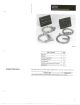
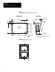
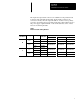
The input and output cable connectors are identified on the printed circuit
board. It is important that the input and output module connectors are
connected correctly, since the output modules do not have reverse polarity
protection. Connecting the wrong cable and module could result in a short to
the power supply output terminals or a blown module fuse. Some of these
fuses are not field replaceable.
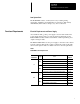
Table 2
Module and Cable Catalog Numbers
No. of PC type Module Type Module Cable Catalog No. based on cable length
Push buttons Catalog No.
1.0 Meter 2.5 Meters 5.0 Meters
Input 1746-IB16 1492-CABLE10B 1492-CABLE25B 1492-CABLE50B
16
SLC
Output 1746-OB16 1492-CABLE10E 1492-CABLE25E 1492-CABLE50E
16
Input 1771-IBD
PLC
Output 1771-OBD
1492-CABLE10F 1492-CABLE25F 1492-CABLE50F
Input 1746-IB32
32
SLC
Output
1746-OB32
1492-CABLE10H 1492-CABLE25H 1492-CABLE50H
Input 1771-IBN 1492-CABLE10J 1492-CABLE25J 1492-CABLE50J
PLC
Output
1771-OBN 1492-CABLE10L 1492-CABLE25L 1492-CABLE50L