
Products

Bulletin 2705
RediPANEL 800A Push Button Modules
User Manual
18
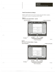
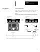
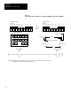
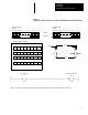
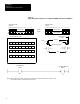
Figure 13
Typical Image Table Configuration for 32 Button RediPANEL with 1771 PLC I/O Modules
PLC Bit Addresses (Octal)
17
00
Bits
17
Push Button #32 Lamp
Push Button #17
00
O:023
I:023
Input
Output
Module Group 3
(Word)
O:023I:023
Module Group (Word)
Rack #2
Lamp Control Bits
WORD 0
Output Image Table
1/4 Rack
Input Image Table
1/4 Rack
WORD 1
012345671011121314151617 012345671011121314151617
Switch Status Bits
Lamp Control Bits
Switch Status Bits
12345678
00 01 02 03 04 05 06 07
9 10111213141516
25 26 27 28 29 30 31 32
17 18 19 20 21 22 23 24
10 11 12 13 14 15 16 17
00 01 02 03 04 05 06 07
10 11 12 13 14 15 16 17
NOTE: This example has push button #17 (at rack 2, word 3, bit 00) turning on lamp #32 (at rack 2, word 3, bit 17).
This example assumes one slot addressing for I/O chassis.