
Manual


Rockwell Automation Publication 520COM-UM004A-EN-E - November 2013 63
Using Multi-Drive Mode Chapter 7
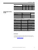
Drive 0 Control Routine
0
5
(End)
Copy File
Source
Dest
Length
Drive_Input_Image[1]
Drive_0_Feedback
1
COP
12
Copy File
Source
Dest
Length
Drive_0_Reference
Drive_Output_Image[1]
1
COP
13
Return from Subroutine
RET
Drive_Input_Image[0].0 Drive_0_Status_Ready
This section takes the data from the input area and moves it to specic tags (Logic Status bits and Feedback) for use
elsewhere in the ladder program.
This section takes the data from specic tags (Logic Command bits and Reference) and moves them to the output
image area for transmission to the master.
1
Drive_Input_Image[0].1 Drive_0_Status_Active
2
Drive_Input_Image[0].3 Drive_0_Status_Forward
3
Drive_Input_Image[0].7 Drive_0_Status_Faulted
4
Drive_Input_Image[0].8 Drive_0_Status_At_Reference
6
Drive_0_Command_Stop Drive_Output_Image[0].0
7
Drive_0_Command_Start Drive_Output_Image[0].1
8
Drive_0_Command_Jog Drive_Output_Image[0].2
9
Drive_0_Command_Clear_Faults Drive_Output_Image[0].3
10
Drive_0_Command_Forward Drive_Output_Image[0].4
11
Drive_0_Command_Forward Drive_Output_Image[0].5
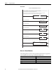
Drive 0 Control Subroutine