User Manual PowerFlex 25-COMM-P PROFIBUS DPV1 Adapter
Important User Information Solid-state equipment has operational characteristics differing from those of electromechanical equipment. Safety Guidelines for the Application, Installation and Maintenance of Solid State Controls (publication SGI-1.1 available from your local Rockwell Automation® sales office or online at http://www.rockwellautomation.com/literature/) describes some important differences between solid-state equipment and hard-wired electromechanical devices.
Table of Contents Preface Overview Recommended Documentation . . . . . . . . . . . . . . . . . . . . . . . . . . . . . . . . . . . . 5 Manual Conventions . . . . . . . . . . . . . . . . . . . . . . . . . . . . . . . . . . . . . . . . . . . . . . 5 Chapter 1 Getting Started Components. . . . . . . . . . . . . . . . . . . . . . . . . . . . . . . . . . . . . . . . . . . . . . . . . . . . . . 7 Features . . . . . . . . . . . . . . . . . . . . . . . . . . . . . . . . . . . . . . . . . . . . . . . . . . . . .
Table of Contents Using Reference/Feedback . . . . . . . . . . . . . . . . . . . . . . . . . . . . . . . . . . . . . . . . 42 Using Datalinks . . . . . . . . . . . . . . . . . . . . . . . . . . . . . . . . . . . . . . . . . . . . . . . . . . 43 I/O Communication . . . . . . . . . . . . . . . . . . . . . . . . . . . . . . . . . . . . . . . . . . . . . 44 Chapter 6 Using Acyclic Messaging About Acyclic Messaging . . . . . . . . . . . . . . . . . . . . . . . . . . . . . . . . . . . . . . . . .
Preface Overview For information on… Recommended Documentation Manual Conventions Recommended Documentation See page… 5 5 All the recommended documentation listed in this section is available online at http://www.rockwellautomation.com/literature. The following publications provide additional information: For... PROFIBUS See... PROFIBUS Standard PROFIBUS Installation Guideline Prosoft Configuration Builder Publication http:// www.profibus.com/ http://www.prosofttechnology.
Preface Overview The following conventions are used throughout this manual: • Parameter names are shown in the format axxx [*]. The a represents the parameter group. The xxx represents the parameter number. The * represents the parameter name— for example C175 [DSI I/O Cfg]. • Menu commands are shown in bold type face and follow the format Menu > Command. For example, if you read “Select File > Open,” you should click the File menu and then click the Open command.
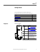
Chapter 1 Getting Started The 25-COMM-P adapter is intended for installation into a PowerFlex 520-series drive and is used for network communication. Topic Components Features Understanding Parameter Types Compatible Products Required Equipment Safety Precautions Quick Start Components Page 7 8 8 9 9 10 11 Components of the Adapter 25-COMM-P Item Part ➊ Node Address switches ➋ ➊ ➋ ➌ ➍ ➍ ➎ ➌ ➎ Description Switches for setting the node address of the adapter.
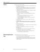
Chapter 1 Getting Started Features The features of the adapter include: • Mounting onto a PowerFlex 520-series drive Control Module back cover for installation into the drive. • Switches to set a node address before applying power to the PowerFlex drive. Alternatively, you can disable the switches and use parameters to configure these functions.
Getting Started Chapter 1 You can view adapter Device parameters and Host parameters with any of the following drive configuration tools: • PowerFlex 520-series drive built-in keypad • PowerFlex 22-HIM-A3 or 22-HIM-C2S HIM • Connected Components Workbench software – click the tab for the adapter at the bottom of the window, and click the Parameters icon in the tool bar.
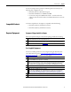
Chapter 1 Getting Started Safety Precautions Please read the following safety precautions carefully. ATTENTION: Risk of injury or death exists. The PowerFlex drive may contain high voltages that can cause injury or death. Remove all power from the PowerFlex drive, and then verify power has been removed before installing or removing an adapter. ATTENTION: Risk of injury or equipment damage exists.
Getting Started Quick Start Chapter 1 This section is provided to help experienced users quickly start using the adapter. If you are unsure how to complete a step, refer to the referenced chapter. Step Action 1 Review the safety precautions for the adapter. 2 Verify that the PowerFlex drive is properly installed. 3 4 5 6 7 8 9 See... Throughout this manual PowerFlex 520-Series Adjustable Frequency AC Drive User Manual, publication 520-UM001 Commission the adapter.
Chapter 1 Getting Started Notes: 12 Rockwell Automation Publication 520COM-UM004A-EN-E - November 2013
Chapter 2 Installing the Adapter This chapter provides instructions for installing the adapter in a PowerFlex 520-series drive. Topic Preparing for an Installation Commissioning the Adapter Connecting the Adapter to the Drive Connecting the Adapter to the Network Network Termination Applying Power Page 13 13 15 18 20 20 Preparing for an Installation Before installing the adapter, do the following: • Read the PROFIBUS Installation Guideline for details on PROFIBUS networks.
Chapter 2 Installing the Adapter Setting the Endianness and Node Address Using the DIP Switches Node Address switches (1...7) Byte Swap switch (8) Set the Endianness of the adapter with Byte Swap switch 8. The Byte Swap switch can be set to either OFF ‘0’ (Little Endian) or ON ‘1’ (Big Endian) data formats for the data exchanged on the network.
Installing the Adapter Chapter 2 Node Address Switch Settings 3 0 0 0 0 1 1 1 1 0 0 0 0 1 1 1 2 0 0 1 1 0 0 1 1 0 0 1 1 0 0 1 1 0 1 0 1 0 1 0 1 0 1 0 1 0 1 0 Node Node Address Switch Address 7 6 5 4 15 0 0 0 1 16 0 0 1 0 17 0 0 1 0 18 0 0 1 0 19 1 0 1 0 20 0 0 1 0 3 1 0 0 0 0 1 2 1 0 0 1 1 0 1 1 0 1 0 1 0 0 0 0 0 1 1 1 0 0 1 1 0 0 1 0 1 0 1 0 1 1 ...
Chapter 2 Installing the Adapter a. Press and hold down the catch on both sides of the frame cover, then pullout and swing upwards to remove (Frames B...E only). b. Press down and slide out the top cover of the control module to unlock it from the power module. c. Hold the sides and top of the control module firmly, then pull out to separate it from the power module.
Installing the Adapter Chapter 2 4. Insert the interface connector for the adapter into the header located at the back of the control module.
Chapter 2 Installing the Adapter 5. Align the Communication card-Drive header on the adapter with the interface connector. Then, press down firmly around the adapter. The adapter snaps into the back of the control module. IMPORTANT The CS1/CS2 terminals on the adapter provide a clean ground for the communication bus cable shields. You should connect the CS1 or CS2 terminal to a clean ground or PE ground on the drive. 6. Attach the control module to the power module.
Installing the Adapter Chapter 2 PROFIBUS Connector 4. Connect the PROFIBUS cable to the adapter and secure it with the two screws on the connector. PROFIBUS communication may not operate correctly if the cable shield does not make full contact with the connector housing.
Chapter 2 Installing the Adapter Wiring Example PowerFlex 525 with 25-COMM-P PowerFlex 525 with 25-COMM-P CompactLogix controller with MVI69-PDPMV1 in slot 1 Sel Esc Sel PROFIBUS Esc PROFIBUS network 6. Connect the other end of the PROFIBUS cable to the PROFIBUS network. Network Termination The first and last node on a PROFIBUS DP Network segment should be terminated. Rockwell Automation recommends that the user select one of the aforementioned PROFIBUS connectors with built-in termination.
Installing the Adapter Chapter 2 Drive and Adapter Status Indicators 25-COMM-P PowerFlex 525 Frame A shown FWD ENET LINK EtherNet/IP ➊ ➍ Item ➊ Status Indicator PORT Esc Sel ➌ Status(1) Green Flashing green ➋ MOD Green Flashing green ➌ NET A Green Flashing green ➍ NET B ➊ ➋ Off ➍ ➋ ➌ Description Normal operation. The adapter is properly connected and is communicating with the drive. The adapter is in the process of establishing a connection to the drive.
Chapter 2 Installing the Adapter TIP The PowerFlex 520-series drive supports up to three control functions and three Reference functions. For more information on how to set different combinations of the control and Reference functions, see the PowerFlex 520-Series Adjustable Frequency AC Drive User Manual, publication 520-UM001.
Chapter 3 Configuring the Adapter This chapter provides instructions and information for setting the parameters to configure the adapter.
Chapter 3 Configuring the Adapter Step Key(s) 1. When power is applied, the last user-selected Basic Display Group parameter number is briefly displayed with flashing characters. The display then defaults to that parameter’s current value. (Example shows the value of b001 [Output Freq] with the drive stopped.) 2. Press Esc to display the Basic Display Group parameter number shown on power-up. The parameter number will flash. Esc Example Display FWD HERTZ FWD 3.
Configuring the Adapter Using the PowerFlex 4-Class HIM to Access Parameters Chapter 3 The PowerFlex 4-class HIM can be used to access parameters in the adapter (see basic steps shown below). It is recommended that you read through the steps for your HIM before performing the sequence. For additional HIM information, refer to the HIM Quick Reference card, publication 22HIM-QR001. Step Key(s) 1. Power up the drive. Then connect the HIM to the DSI port of the drive.
Chapter 3 Configuring the Adapter Using Master-Slave Hierarchy (Optional) This procedure is only required if Datalinks are used to write or read data of the drive. A hierarchy determines the type of device with which the adapter exchanges data. In a Master-Slave hierarchy, the adapter exchanges data with a PROFIBUS master, such as a Prosoft MVI69-PDPMV1 Master Network Interface module for CompactLogix.
Configuring the Adapter Chapter 3 Enabling Datalinks To Read Data IMPORTANT Always use the Datalink parameters in consecutive numerical order, starting with the first parameter. For example, use Host parameters C161, C162, and C163 to configure three Datalinks to read data. Otherwise, the network I/O connection will be larger than necessary, which needlessly increases controller response time and memory usage.
Chapter 3 Configuring the Adapter Changing the Fault Action Set the values of Device parameters 11 [Comm Flt Action] and 12 [Idle Flt Action] to the desired responses: Value 0 1 Action Fault Stop 2 3 4 Zero Data Hold Last Send Flt Cfg Description The drive is faulted and stopped. Datalink data is no longer sent to the drive. (Default) The drive is stopped as per Host parameter P045 [Stop Mode] setting. Datalink data sent to the drive remains unchanged.
Configuring the Adapter Chapter 3 When you enter 1 “Reset Module”, the adapter will be immediately reset. An alternate method to reset the adapter is by power cycling the drive. Set Device parameter 19 [Reset Module] to 2 “Set Defaults”. Restoring Adapter Parameters to Factory Defaults Value 0 1 2 Description Ready (Default) Reset Module Set Defaults When you enter 2 “Set Defaults”, the adapter will set all of its parameters to their factory default values.
Chapter 3 Configuring the Adapter To obtain a firmware update for this adapter, go to http://www.ab.com/support/ abdrives/webupdate.
Chapter 4 Configuring the PROFIBUS Master PROFIBUS masters are available from several manufacturers, including ProSoft Technology. This chapter provides instructions on how to use the MVI69PDPMV1 PROFIBUS DPV1 master and do the following: • Configure the MVI69-PDPMV1 PROFIBUS DPV1 master. • Install the 25-COMM-P GSD file in the software tool library. • Configure the 25-COMM-P adapter as a PowerFlex 520-series PROFIBUS slave.
Chapter 4 Configuring the PROFIBUS Master Configuring the MVI69PDPMV1 PROFIBUS DPV1 Master To begin, launch the ProSoft Configuration Builder (PCB) software, which has a window consisting of a treeview on the left, and information and configuration panes on the right. When you first launch PCB software, the treeview consists of folders for Default Project and Default Location, with a Default Module in the Default Location folder. The ProSoft Configuration Builder window below shows a new project.
Configuring the PROFIBUS Master Chapter 4 3. For the selected MVI69-PDPMV1 module, there is a default list of ports as shown in the example window below. 4. In the PCB treeview, click ‘+’ to expand the MVI69-PDPMV1 tree. 5. Right-click the PROFIBUS DP icon and choose Configure. The PROFIBUS Master Setup dialog box appears. 6.
Chapter 4 Configuring the PROFIBUS Master 7. After choosing 1769 E3xE, click Configure PROFIBUS. The ProSoft Configuration Builder for PROFIBUS MVI69-PDPMV1 configuration tool appears. Installing GSD Files ProSoft Configuration Builder (PCB) software uses PROFIBUS slave definition files (GSD files) to obtain basic configuration information about the PROFIBUS slaves you add to the network.
Configuring the PROFIBUS Master Chapter 4 1. From the Tools menu, choose Install new GS*-file. A dialog box appears for you to browse for the location of the GSD file. 2. Select the file to install, and click Open. If the file already exists in the configuration file path, you will be prompted to overwrite the file. 3. You will be prompted to associate the GSD configuration file with a bitmap image of the slave. 4. Use the File/Open dialog box to browse for the location of the image file(s) to use.
Chapter 4 Configuring the PROFIBUS Master Configuring the Adapter as a Slave Follow these steps to add and configure a 25-COMM-P adapter as a slave. 1. Drag the Slave icon into the Bus Configuration window. The slave is added to the PROFIBUS network and configured to the Master in a networked relationship. 2. In the treeview, click ‘+’ to expand the slave you added. The list in the window above shows the possible input/output configuration values for a 25-COMM-P Slave. The Datalinks (1...
Configuring the PROFIBUS Master Chapter 4 4. Drag the input and output parameters to the Slot Location Grid (Subscriber List) below the Bus Configuration window. This view displays the slot number, configuration data, and starting input and output addresses that will be assigned in the controller memory for the MVI69-PDPMV1 Master. The Master uses this information to identify and communicate with individual slaves on the network.
Chapter 4 Configuring the PROFIBUS Master 5. Double-click the Slave icon to view the Slave Properties, or right-click the slave icon and select Object Properties. The PCB software automatically assigns a PROFIBUS address to each new slave. The address assignment begins at address 3, and is incremented by 1 for each new slave added to the network. 6. You can change the address in the Common tab of the Slave properties dialog box.
Configuring the PROFIBUS Master Chapter 4 7. Click on the Parameter assignment tab. 8. Click the value for the DP Mode parameter in the value column. From the pull-down menu, choose DPV1 (default). 9. Click the value for the Diagnostic Alarm parameter in the value column. From the pull-down menu, choose Enabled. Downloading the Project to the Module Follow these steps to download the project to the MVI69-PDPMV1 Master. 1. In the Online menu, select Download Configuration.
Chapter 4 Configuring the PROFIBUS Master 2. From the Select Connection Type pull-down menu, choose 1769 L3xE. The default path appears in the text box. 3. Click DOWNLOAD to start downloading the project to the MVI69PDPMV1 Master. 4. After the configuration is transferred, it will automatically start rebooting the MVI69-PDPMV1 Master. 5. After the MVI69-PDPMV1 Master has been rebooted, you can view the status of the download.
Chapter 5 Using the I/O This chapter provides information and examples that explain how to control, configure, and monitor a PowerFlex 520-series drive using PROFIBUS DPV0 messaging. Topic About I/O Messaging Understanding the I/O Image Using Logic Command/Status Using Reference/Feedback Using Datalinks I/O Communication Page 41 42 42 42 43 44 ATTENTION: Risk of injury or equipment damage exists. The examples in this publication are intended solely for purposes of example.
Chapter 5 Using the I/O Understanding the I/O Image The terms input and output are defined from the controller’s point of view. Therefore, output I/O is data that is produced by the controller and consumed by the adapter. Input I/O is status data that is produced by the adapter and consumed as input by the controller. The I/O image will vary based on how many of the drive’s 16-bit Datalinks (Host parameters C161...C164 [Opt Data In 1...4] and C165...C168 [Opt Data Out 1...4]) are used.
Using the I/O Chapter 5 P044 [Maximum Freq]. PowerFlex 520-Series Drive Example Speed Reference/ Feedback Scaling on page 43 shows example References and their results for a PowerFlex 520-series drive that has its: • Host parameter P043 [Minimum Freq] set to 10.00 Hz. • Host parameter P044 [Maximum Freq] set to 50.00 Hz. PowerFlex 520-Series Drive Example Speed Reference/Feedback Scaling Network Reference Value 10000 6500 3250 0 Speed Commanded Value 100.00 Hz 65.00 Hz 32.50 Hz 0.00 Hz Output Speed 50.
Chapter 5 Using the I/O makeup of the I/O connection in a running system. The I/O connection with the controller must first be disabled to allow changes to the respective Datalinks.
Using the I/O Chapter 5 Output Mapping in the MVI69-PDPMV1 The input and output data can also be viewed through the ProSoft Configuration Builder tool, while in the Monitor/Modify mode of operation. The PowerFlex 520-series drive data is displayed under the value column for each the configured PROFIBUS modules by selecting the Online slave properties tab as shown in Online Slave Properties on page 45.
Chapter 5 Using the I/O Notes: 46 Rockwell Automation Publication 520COM-UM004A-EN-E - November 2013
Chapter 6 Using Acyclic Messaging This chapter provides information and examples that explain how to use PROFIBUS Class 1 DPV1 Acyclic Messaging to configure and monitor the adapter installed and connected to the PowerFlex 520-series drive. Topic About Acyclic Messaging Acyclic Messaging for DPV1 Class Acyclic Messaging Examples Page 47 49 49 ATTENTION: Risk of injury or equipment damage exists. The examples in this publication are intended solely for purposes of example.
Chapter 6 Using Acyclic Messaging PROFIBUS Slot and Index for Drive and Adapter Parameters PROFIBUS Slot 0x00 0x01... 0x04 0x05... 0x08 0x09... 0x0C 0x0D...0x10 0x11...0x14 0x15...0x18 0x19 >0x1A PROFIBUS Index 0x00...0xFF 0x00...0xFF 0x00...0xFF 0x00...0xFF 0x00...0xFF 0x00...0xFF 0x00...0xFF 0x00...0xFF 0x00...
Using Acyclic Messaging Chapter 6 Acyclic Messaging for DPV1 Class The 25-COMM-P adapter provides the following PROFIBUS DPV1 Class 1 Acyclic Services: • READ – This service is used to read a parameter in the PowerFlex 520series drive or the adapter. • WRITE – This service is used to write a parameter in the PowerFlex 520series drive or the adapter.
Chapter 6 Using Acyclic Messaging Class 1 Acyclic Read for Host Parameter 1 [Output Freq] Change value of tag to “1” to send Class 1 Acyclic Read Command. Copy or insert values for parameter read request: - Parameter Slot Number - Slave Node Address - Length of Data (Bytes) - Parameter Index When the message response successfully returns, the data for the Output Frequency parameter will be placed in the tags MVI69PDPMV1.Mailbox.Class1AcyclicRead.In.Data[] byte array.
Using Acyclic Messaging Chapter 6 Class 1 Acyclic Read Response Data for Host Parameter 1 [Output Freq] Response Data from command reading the Frequency Reference of the PF520-series drive. The Error Decode is indicating “No Error”. The Error Decode Tag is “Non-Zero” if an error occurred in the command response. Class 1 Acyclic Read Command Response Data. By copying this data to a “Local Program Tag” with a data type specification of “INT” the value will read: 45.00 Hz after the conversion.
Chapter 6 Using Acyclic Messaging Write Example for Host Parameter 41 [Accel Time 1] To write to the PowerFlex 520-series drive parameter 41[Accel Time 1] using a Class 1 Acyclic Write Service, setup a CompactLogix controller (with a MVI69PDPMV1 PROFIBUS Master). After the master is setup, the CompactLogix tags must be populated with the correct slot and index addressing values to write the parameter as shown in Class 1 Acyclic Write for Host Parameter 41 [Accel Time 1] on page 53.
Using Acyclic Messaging Chapter 6 Class 1 Acyclic Write for Host Parameter 41 [Accel Time 1] Copy or insert values for parameter write request: - Parameter Slot Number - Slave Node Address - Length of Data (Bytes) - Parameter Index - Data bytes... (Data bytes may be copied from a “Local PLC Tag” with appropriate data type specification) Change value of tag to “1” to send Class 1 Acyclic Write Command. To manually trigger the message to be sent, enter a value of ‘1’ into the MVI69PDPMV1.MailboxCommand.
Chapter 6 Using Acyclic Messaging Class 1 Acyclic Write Response Data for Host Parameter 41 [Accel Time 1] Response Data from command writing the parameter is returned as indication of what parameter request occurred. Response Data from command writing the Accel Time 1 Parameter of the PF520-series drive. The Error Decode is indicating “No Error”. The Error Decode Tag is “Non-Zero” if an error occurred in the command response.
Chapter 7 Using Multi-Drive Mode This chapter provides instructions on how to configure a CompactLogix controller to use the PowerFlex 520-series drive in Multi-drive mode. Topic Single-Drive Mode vs.
Chapter 7 Using Multi-Drive Mode For the examples in the chapter, we will use the PowerFlex 525 as a master drive with four daisy-chained PowerFlex 4M drives.
Using Multi-Drive Mode Chapter 7 • Since the RS-485 ports are used for daisy-chaining the drives, there is no connection for a peripheral device such as a HIM or USB converter module (1203-USB). DSI Splitter cables cannot be used to add a second connection for a peripheral device. To daisy-chain the drives to the PowerFlex 525, the AK-U0-RJ45-TB2P terminal block connector can be used for easy installation.
Chapter 7 Using Multi-Drive Mode Multi-Drive Example of I/O Image PROFIBUS Controller DSI Scanner Adapter Word and I/O Word 0 Word 1 Word 2 Word 3 Word 4 Word 5 Logic Command Reference Logic Command Reference Logic Command Reference Drive 3 Word 6 Word 7 Logic Command Reference PowerFlex Drive 3 Drive 4 Word 8 Word 9 Logic Command Reference PowerFlex Drive 4 Word 0 Word 1 Word 2 Word 3 Word 4 Word 5 Logic Status Feedback Logic Status Feedback Logic Status Feedback Drive 3 Word 6 Word 7 Lo
Using Multi-Drive Mode IMPORTANT Chapter 7 Parameters [Comm Loss Action] and [Comm Loss Time] in the daisy-chained drives are still used in Multi-drive mode. If the RS-485 cable is disconnected or broken, the disconnected drive(s) will take the corresponding Comm Loss Action(s). On the PROFIBUS side, Device parameters 11 [Comm Flt Action] and 12 [Idle Flt Action] determine the action taken for ALL of the drives on the Multi-drive node.
Chapter 7 Using Multi-Drive Mode Multi-Drive Ladder Logic Program for Generic Profile The following is an example of the ladder logic program for the Generic Profile and demonstrates using Multi-drive mode with five drives. See Multi-Drive Mode Example for Network on page 56 for an example of a system layout diagram. See Multi-Drive Example of I/O Image on page 58 for the number of 16-bit input and output words to use for your application.
Using Multi-Drive Mode Parameter C303 [Comm Node Addr] C304 [Comm Loss Action] C305 [Comm Loss Time] C306 [Comm Format] CompactLogix Controller Example Drive 1 1 0 5.0 s 0 Drive 2 2 0 5.0 s 0 Value Drive 3 3 0 5.0 s 0 Chapter 7 Drive 4 4 0 5.0 s 0 The following common Tags are used: Tag Name MVI69PDPMV1.Input MVI69PDPMV1.
Chapter 7 Using Multi-Drive Mode Main Routine PowerFlex 525 PROFIBUS DP Multi-Drive Demo CompactLogix Multi-Drive example program with a PowerFlex 525 on PROFIBUS DP. Four PowerFlex 4M drives are daisy-chained to the main PowerFlex 525 using their RJ45 ports (RS-485). In this mode, up to five PowerFlex drives can exist on one PROFIBUS DP node.
Using Multi-Drive Mode Chapter 7 Drive 0 Control Routine Drive 0 Control Subroutine This section takes the data from the input area and moves it to specific tags (Logic Status bits and Feedback) for use elsewhere in the ladder program. Drive_Input_Image[0].0 Drive_0_Status_Ready Drive_Input_Image[0].1 Drive_0_Status_Active Drive_Input_Image[0].3 Drive_0_Status_Forward Drive_Input_Image[0].7 Drive_0_Status_Faulted Drive_Input_Image[0].
Chapter 7 Using Multi-Drive Mode Drive 1 Control Routine Drive 1 Control Subroutine This section takes the data from the input area and moves it to specific tags (Logic Status bits and Feedback) for use elsewhere in the ladder program. Drive_Input_Image[2].0 Drive_1_Status_Ready Drive_Input_Image[2].1 Drive_1_Status_Active Drive_Input_Image[2].3 Drive_1_Status_Forward 0 1 2 Drive_Input_Image[2].7 Drive_1_Status_Faulted Drive_Input_Image[2].
Using Multi-Drive Mode Chapter 7 Drive 2 Control Routine Drive 2 Control Subroutine This section takes the data from the input area and moves it to specific tags (Logic Status bits and Feedback) for use elsewhere in the ladder program. Drive_Input_Image[4].0 Drive_2_Status_Ready Drive_Input_Image[4].1 Drive_2_Status_Active Drive_Input_Image[4].3 Drive_2_Status_Forward 0 1 2 Drive_Input_Image[4].7 Drive_2_Status_Faulted Drive_Input_Image[4].
Chapter 7 Using Multi-Drive Mode Drive 3 Control Routine Drive 3 Control Subroutine This section takes the data from the input area and moves it to specific tags (Logic Status bits and Feedback) for use elsewhere in the ladder program. Drive_Input_Image[6].0 Drive_3_Status_Ready Drive_Input_Image[6].1 Drive_3_Status_Active Drive_Input_Image[6].3 Drive_3_Status_Forward 0 1 2 Drive_Input_Image[6].7 Drive_3_Status_Faulted Drive_Input_Image[6].
Using Multi-Drive Mode Chapter 7 Drive 4 Control Routine Drive 4 Control Subroutine This section takes the data from the input area and moves it to specific tags (Logic Status bits and Feedback) for use elsewhere in the ladder program. Drive_Input_Image[8].0 Drive_4_Status_Ready Drive_Input_Image[8].1 Drive_4_Status_Active Drive_Input_Image[8].3 Drive_4_Status_Forward 0 1 2 Drive_Input_Image[8].7 Drive_4_Status_Faulted Drive_Input_Image[8].
Chapter 7 Using Multi-Drive Mode For example, to access [Accel Time 1] (parameter P041 in PowerFlex 525 and P109 in PowerFlex 4M) in each of the drives, the following slot and index values would be used: • Drive 0 (PowerFlex 525) Slot = 1, Index = 41 • Drive 1 (PowerFlex 4M) Slot = 5, Index = 109 • Drive 2 (PowerFlex 4M) Slot = 9, Index = 109 • Drive 3 (PowerFlex 4M) Slot = 13, Index = 109 • Drive 4 (PowerFlex 4M) Slot = 17, Index = 109 Additional Information 68 • When the PowerFlex 525 drive (Drive 0)
Chapter 8 Troubleshooting This chapter provides information for diagnosing and troubleshooting potential problems with the adapter and network. Topic Understanding the Status Indicators PORT Status Indicator MOD Status Indicator NET A Status Indicator Viewing Adapter Diagnostic Items Viewing and Clearing Events Understanding the Status Indicators Page 69 70 70 70 71 71 The adapter has four status indicators. They can be viewed on the adapter or through the drive cover.
Chapter 8 Troubleshooting PORT Status Indicator This red/green bicolor LED indicates the status of the adapter’s connection to the drive as shown in the table below. Status Off Cause The adapter is not powered. Flashing red The adapter is not receiving communication from the drive, or a drive is missing in Multi-drive mode. The adapter is establishing communications with the drive. The adapter is properly connected and is communicating with the drive.
Troubleshooting Viewing Adapter Diagnostic Items Chapter 8 If you encounter unexpected communications problems, the adapter’s diagnostic items may help you or Rockwell Automation personnel troubleshoot the problem. The diagnostic parameters for the adapter can be viewed using the PowerFlex 22-HIM-A3/-C2S HIM or Connected Components Workbench software. Adapter Diagnostic Items in Single-Drive Mode No. 01 02 Name Reserved Logic Cmd 03 04 05 06 07...
Chapter 8 Troubleshooting Resetting the adapter to defaults has no effect on the event queue, other than to log a Code 58 “Module Defaulted” event. Many events in the event queue occur under normal operation. If you encounter unexpected communications problems, the events may help you or Allen-Bradley personnel troubleshoot the problem.
Troubleshooting Chapter 8 Adapter Events Code 63 64 65 Event Net Clear Cmd Net Set Params Net WD Timeout Description The adapter received a PROFIBUS “Clear Command” from the network master. The adapter received a PROFIBUS “Set Parameters” from the network master. The PROFIBUS ASIC has declared a network timeout.
Chapter 8 Troubleshooting Notes: 74 Rockwell Automation Publication 520COM-UM004A-EN-E - November 2013
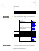
Appendix A Specifications Appendix A presents the specifications for the adapter. Communications Electrical Mechanical Environmental Regulatory Compliance Network Protocol Data Rates Media Profibus 9.6K, 19.2K, 45.45K, 93.75K, 187.5K, 500K, 1.5M, 3M, 6M, and 12M The adapter has auto baud rate detection. Profibus cable with DB9 connector Consumption Drive Network 150 mA @ 5V supplied through the drive None Dimensions Height Length Width Weight 23.5 mm (0.93 in.) 138.3 mm (5.44 in.) 66.8 mm (2.
Appendix A Specifications Notes: 76 Rockwell Automation Publication 520COM-UM004A-EN-E - November 2013
Appendix B Adapter Parameters Appendix B provides information about the adapter parameters. Topic Device Parameters Page 77 The adapter parameters are displayed in a Numbered List view order. Device Parameters Parameter No. Name and Description Details 01 [MultiDrv Sel] Values: Displays the single-drive or multi-drive operating mode based on Host parameter C169 [MultiDrv Sel] setting.
Appendix B Adapter Parameters Parameter No. Name and Description 08 [Net Rate Actual] Displays the actual speed (bps) for the adapter’s Profibus network port. 09 10 11 Details Values: Type: [Profibus DP State] Values: Displays the current state of Profibus DP communications with the master. [Profibus Mode] Displays the Profibus operation mode selected by the user using the mode selection jumper. This will either be Normal or PROFIdrive. Important: PROFIdrive is not supported in this version.
Adapter Parameters Parameter No. Name and Description Details 12 [Idle Flt Action] Default: Sets the action that the adapter and drive will take if the Values: adapter detects that the controller is in program mode or faulted. This setting is effective only if I/O that controls the drive is transmitted through the adapter. When the controller is put back in Run mode, the drive will automatically receive commands over the network again.
Appendix B Adapter Parameters Parameter No. Name and Description Details 19 [Reset Module] Default: No action if set to 0 “Ready”. Resets the adapter if set to 1 “Reset Values: Module”. Restores the adapter to its factory default settings if set to 2 “Set Defaults”. This parameter is a command. It will be reset to 0 “Ready” after the command has been performed. Type: Reset Required: 0 = Ready 0 = Ready 1 = Reset Module 2 = Set Defaults Read/Write No ATTENTION: Risk of injury or equipment damage exists.
Appendix C Logic Command/Status Words: PowerFlex 520Series Drives Appendix C presents the definitions of the Logic Command and Logic Status words that are used for PowerFlex 520-series drives. PowerFlex 523 drives support only Velocity bit definitions. PowerFlex 525 drives can use Host parameter C122 [Cmd Stat Select] to select either Velocity or Position bit definitions.
Appendix C Logic Command/Status Words: PowerFlex 520-Series Drives Position Bit Definitions Comm Logic Command – C122 = 1 “Position” Logic Bits 15 14 13 12 11 10 9 8 7 6 5 4 3 2 1 0 x Start(1) x Jog 1(2) x Clear Fault(3) x x x Unipolar Direction x Logic Input 1 Logic Input 2 Frequency and Position Steps x x x Command Normal Stop x x Find Home Hold Step Redefine Position Enable Sync Disable Travel x x x x Description 0 = Not Normal Stop 1 = Normal Stop 0 = Not Start 1 = Start 0 = No
Logic Command/Status Words: PowerFlex 520-Series Drives Appendix C Position Bit Definitions Comm Logic Status – C122 = 1 “Position” Logic Bits 15 14 13 12 11 10 9 8 7 6 5 4 3 2 1 x x x x x x x x x x x x x x x 0 x Command Run Ready Active Command Direction Actual Direction Accel Decel Travel Position Fault At Speed At Position Drive Home Commanded Home Sync Hold Sync Ramp Traverse Traverse Decel Rockwell Automation Publication 520COM-UM004A-EN-E - November 2013 Description 0 = Not Ready to Run 1
Appendix C Logic Command/Status Words: PowerFlex 520-Series Drives Notes: 84 Rockwell Automation Publication 520COM-UM004A-EN-E - November 2013
Glossary The following terms and abbreviations are used throughout this manual. For definitions of terms not listed here, see the Allen-Bradley Industrial Automation Glossary, publication AG-7.1. Adapter Devices such as drives, controllers, and computers usually require an adapter to provide a communication interface between them and a network such as PROFIBUS. An adapter reads data on the network and transmits it to the connected device. It also reads data in the device and transmits it to the network.
Glossary Data Rate The speed at which data is transferred on the PROFIBUS network. The available data rates depend on the type of cable and total cable length used on the network. Data Rate 9.6 K 19.2 K 45.45 K 93.75 K 187.5 K Maximum Cable Length 1000 m (3,280 ft) 1000 m (3,280 ft) 1000 m (3,280 ft) 1000 m (3,280 ft) 1000 m (3,280 ft) Data Rate 500 K 1.
Glossary I/O Data I/O data, sometimes called “implicit messages” or “input/output,” is time-critical data such as a Logic Command and Reference. The terms “input” (To Net) and “output” (From Net) are defined from the controller’s point of view. Output is produced by the controller and consumed by the adapter. Input is produced by the adapter and consumed by the controller. Logic Command/Logic Status The Logic Command is used to control the PowerFlex 520-series drive (for example, start, stop, direction).
Glossary PROFIBUS Network A PROFIBUS network uses RS485 to connect devices such as controllers, drives, motor starters and other equipment in automation systems. A Profibus network can support a maximum of 126 devices. Each device is assigned a unique node address and transmits data on the network at the same data rate. A cable is used to connect devices on the network. It contains the bus signal. Devices can be connected to the network in a daisy-chain connection.
Glossary Update The process of updating firmware in a device. The adapter can be updated using various Allen-Bradley software tools. See Updating the Adapter Firmware on page 29 for more information. Zero Data When communications are disrupted (for example, a cable is disconnected), the adapter and drive can respond with zero data. Zero data results in the drive receiving zero as values for Logic Command, Reference, and Datalink data.
Glossary Notes: 90 Rockwell Automation Publication 520COM-UM004A-EN-E - November 2013
Index A acyclic messaging about, 47 definition, 85 multi-drive mode, 67 adapter applying power, 20 commissioning, 13 components, 7 configuration tools, 23 connecting to the drive, 15 connecting to the network, 18 definition, 85 diagnostic items, 71 events, 71 features, 8 list of parameters, 77 preparing for installation, 13 resetting, 28 single-drive/multi-drive mode, 55 specifications, 75 status indicators, 21, 69 troubleshooting, 69 viewing status, 29 F fault action changing the, 28 definition, 86 settin
Index node address definition, 87 setting with a parameter, 25 setting with switches, 14 NVS (Non-Volatile Storage) definition, 87 in drive, 43 P parameters accessing with drive keypad, 23 accessing with HIM, 25 convention used in manual, 6 list of, 77 restoring to factory default values, 29 PROFIBUS cable, 19 connector, 7, 18 data rate, 75 network definition, 88 network example for single-drive/multi-drive mode, 55, 56 specification, 88 ProSoft Configuration Builder (PCB) software, 88 Q in I/O image, 4
Rockwell Automation Support Rockwell Automation provides technical information on the Web to assist you in using its products. At http://www.rockwellautomation.com/support/, you can find technical manuals, a knowledge base of FAQs, technical and application notes, sample code and links to software service packs, and a MySupport feature that you can customize to make the best use of these tools.