
Instruction Manual

PowerFlex 520-Series Communication Adapters
Publication 520COM-IN001C-EN-P - July 2014
Supersedes Publication 520COM-IN001B-EN-P - September 2013 Copyright © 2014 Rockwell Automation, Inc. All rights reserved.
Allen-Bradley, Rockwell Software, Rockwell Automation, PowerFlex, and TechConnect are trademarks of Rockwell Automation, Inc.
Trademarks not belonging to Rockwell Automation are property of their respective companies.
U.S. Allen-Bradley Drives Technical Support - Tel: (1) 262.512.8176, Fax: (1) 262.512.2222, E-mail: support@drives.ra.rockwell.com
Online: www.ab.com/support/abdrives
5
4
3
2
1
Red
White
Bare
Blue
Black
4
5
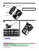
Terminal Color Signal Function
5 Red V+ Power Supply
4 White CAN_H Signal High
3BareSHIELDShield
2 Blue CAN_L Signal Low
1 Black V- Common
Maximum Wire Size Minimum Wire Size Torque
3.33 mm
2
(12 AWG) 0.08 mm
2
(28 AWG) 0.44...0.54 Nm (3.9...4.8 lb-in)
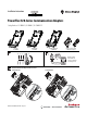
Wiring the DeviceNet Adapter How to Remove the Control Module Back Cover if Required
25-COMM-D
25-COMM-P
25-COMM-E2P
Install the Communication Adapter
DeviceNet adapter with optional 25-ENC-1
Incremental Encoder Input shown
Communication adapter label
(pre-attached)
Space for optional Incremental
Encoder Input label
Note: Incremental Encoder Input is for PowerFlex 525 only.
You can install both the communication adapter and optional
Incremental Encoder Input on the same Control Module Back Cover.