
User Manual


Rockwell Automation Publication 20P-UM001K-EN-P - July 2014 81
Installation and Wiring Chapter 1
I/O Signal and Control Wiring
Eight (8) digital inputs, four (4) digital outputs, three (3) analog inputs, and two
(2) analog outputs are available on the standard I/O terminal blocks provided
with the drive. One digital input (1…8) must be configured for “Enable” (digital
input 4 by default = “Enable”). See I/O and Control Wire Routing on page 89
for information on routing I/O signal and control wires.
Additional digital and analog I/O is available when the optional I/O expansion
circuit board is installed. See Appendix F
for more information. Also, you can use
the optional 115V AC Converter circuit board to convert 115V AC digital input
signals to 24V DC digital inputs signals to interface with the digital inputs on the
standard I/O terminal blocks. See Appendix G
for more information.
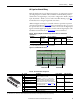
Table 33 - Analog I/O, Digital I/O and DC Analog Tachometer Wire Sizes and Terminal
Specifications
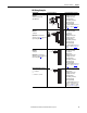
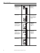
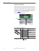
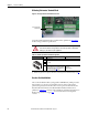
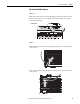
Figure 58 - I/O Terminal Block Locations
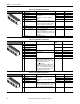
Table 34 - I/O Terminal Block 1 Designations
Signal Type Terminal Block
(Terminals)
Wire Size and Type
(1)
(1) See Cable and Wiring Recommendations on page 43 for more information.
Tightening
Torque
N•m (lb•in)
Flexible (mm
2
)Multi-core
(mm
2
)
AWG
Analog and Digital I/O TB1…4 (1…40)
0.140…1.500 0.140…1.500 26…16 0.4 (3.5)
DC Analog Tach M3 (+ and –)
Terminal Block 3
Terminal Block 1
Terminal Block 4
Terminal Block 2
No. Signal Description Factory Default Config. Parameter
1 Analog Input 1 (+) Isolated
(1)
, bipolar, differential
±10V / 0…20 mA or 4…20 mA.
Important: 0…20 mA or 4…20 mA operation
requires that switch S9, S10, and S11 on the control
board be in the “Off” position. Drive damage may
occur if the switch is not in the correct position based
on the type of input signal. See Table 27
on page 54.
Max ±10V, Max 0.25 mA.
1 “Speed Ref A” 70 [Anlg In1 Sel]
2 Analog Input 1 (–)
3 Analog Input 2 (+) 0 “Off” 75 [Anlg In2 Sel]
4 Analog Input 2 (–)
5 Analog Input 3 (+) 0 “Off” 80 [Anlg In3 Sel]
6 Analog Input 3 (–)
7 +10V Pot Reference 2…5 kΩ load. Max ±10V, 10 mA. – –
8 –10V Pot Reference
9 Pot Common For (+) and (–) 10V pot references. – –
10 PE ground PE ground to drive chassis. – –
(1) Differential Isolation - External source must be maintained at less than 160V with respect to PE. Input provides high common mode immunity.
2
3
4
5
1
7
8
9
10
6