
User Manual

Rockwell Automation Publication 20P-UM001K-EN-P - July 2014 77
Installation and Wiring Chapter 1
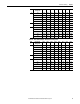
DIP Switch S4 Settings
DIP switch S4 must be configured to be greater than or equal to the maximum
DC input voltage. Maximum DC Input Voltage = (Tach Volts/1000 rpm) x Par
45 [Max Ref Speed] x 1.1. See Drive Reference and Feedback Scaling on page
279
for details on programming speed feedback values.
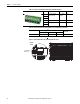
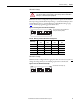
Figure 56 - DC Analog Tachometer DIP Switch S4 Example
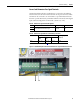
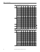
Table 28 - DC Analog Tachometer DIP Switch S4 Configuration
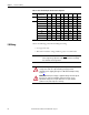
DIP Switch S15 Settings
DIP Switch S15 is configured for the appropriate drive size at the factory. Do not
change the settings unless you are installing a replacement control board.
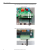
Figure 57 - Drive Size DIP Switch S15 Example
ATTENTION: The drive can overspeed if DIP switch S4 is set incorrectly or the
tachometer is wired incorrectly. Failure to observe this precaution could result in
damage to, or destruction of, the equipment.
Maximum DC
Input Voltage
S4-1
S4-8
S4-2
S4-7
S4-3
S4-6
S4-4
S4-5
22V ON ON ON ON
45V ONONONOFF
90V ON ON OFF OFF
180V ON OFF OFF OFF
300V OFF OFF OFF OFF
1
ON
2
3 4
5
6
78
DIP
Note: The illustration depicts the DIP switch
settings for 90V (factory default).
1
ON
2
3 4
5
6
78
DIP
Note: Illustration for example only.