
User Manual

76 Rockwell Automation Publication 20P-UM001K-EN-P - July 2014
Chapter 1 Installation and Wiring
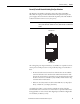
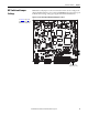
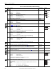
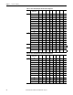
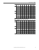
Table 27 - Control Circuit Board Jumper and DIP Switch Settings
ID Jumper/
Switch
Function Factory Default Example
S0 For factory boot flashing only. Leave set to the factory setting. Jumper Off
Jumper On Firmware boot
Jumper Off Normal function
S1 For factory boot flashing only. Leave set to the factory setting. Jumper Off
Jumper On Write firmware boot code
Jumper Off Boot code on flash is protected
S2 Not used. Leave set to the factory setting. Jumper Off
S3 For factory boot flashing only. Leave set to the factory setting. Jumper Off
Jumper On Reset
Jumper Off Normal function
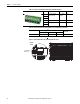
S4 Configures the input voltage of the DC analog tachometer.
See Table 28
on page 77 for configuration.
90V –
S9 Configures the input signal of Analog Input 1 (terminals 1 and 2): On
Off Position 0…20 mA / 4…20 mA
On Position 0…10V / ±10V
Note: The input signal type must also be programmed accordingly in Par 71 [Anlg In1 Config].
S10 Configures the input signal of Analog Input 2 (terminal 3 and 4): On
Off Position 0…20 mA / 4…20 mA
On Position 0…10V / ±10V
Note: The input signal type must also be programmed accordingly in Par 76 [Anlg In2 Config].
S11 Configures the input signal of Analog Input 3 (terminals 5 and 6): On
Off Position 0…20 mA / 4…20 mA
On Position 0…10V / ±10V
Note: The input signal type must also be programmed accordingly in Par 81 [Anlg In3 Config].
S12 Not used. Leave set to the factory setting. Off –
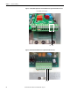
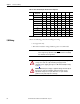
S14 Field current resistors setting, see Field Current Configuration on page 60
.
The value selected with switch S14 must be entered in Par 374 [Drv Fld Brdg Cur] when the drive is
commissioned. For permanent magnet motor applications, leave set to the factory default settings.
Minimum field
current rating based
on drive size.
–
S15 Configuration of the control circuit board to the appropriate drive size. Leave set to the factory setting, unless the
control board has been supplied as a spare part. See DIP Switch S15 Settings on page 77
for switch configuration
based on drive current rating code.
Armature current
based on drive size.
–
S18 Not used. Leave set to the factory setting. Off –
S20 Monitoring of the Z channel of the Digital Encoder on connector XE2: On
Off Position Z channel monitored
On Position Z channel not monitored
The S20 setting must match the value selected in Par 652 [Encoder Err Chk].
For example, if S20 = “Off”, then Par 652 = 1 “Enabled”.
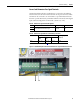
S21 Encoder power supply voltage and input selection:
This switch setting determines both the power supply (input) and feedback level (output) voltage of the
connected encoder.
Note: When control power is supplied to the drive, the appropriate LED lights to indicate the selection of the
switch.
12…5 V
ENC_5 +5 V encoder (+2.5…5.4V input range)
ENC_12 +12…15 V encoder (+5.4V…15.2V input range)
1
= ON
= OFF
=OFF
2
3
= ON
= OFF
4
5
6
7
8
= ON
= OFF
9
= 12-15V
= 5V
ENC_5 ENC_12
ENC_5 ENC_12