
User Manual

Rockwell Automation Publication 20P-UM001K-EN-P - July 2014 65
Installation and Wiring Chapter 1
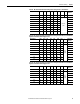
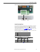
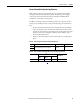
Figure 41 - Frame D Relay and Thermistor/Thermal Switch Terminal Block Locations
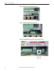
Control Circuit Input Power
The control circuit must be powered by a clean, external 230V AC or 115V AC
single phase power supply. For frame B and C drives only
, a jumper is required
between terminals SA and SB for 115V AC control input power. For frame B
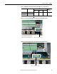
drive SA-SB terminal block location, see Figure 47
on page 68. For frame C drive
SA-SB terminal block location, see Figure 47
on page 68.
Note: If the SA-SB terminal block is not configured for the correct input voltage,
“No Fault” (F0) displays on the HIM, if installed.
Table 20 - Control Circuit Wire Sizes and Terminal Specifications
Terminals Description
U2, V2 Single phase AC power for the control circuits
PE Safety ground (on frame C drive terminal blocks only)
Terminals Wire Size and Type
(1)
(1) See Cable and Wiring Recommendations on page 43 for more information.
Tightening Torque
N•m (lb•in)
Flexible
(mm
2
)
Multi-core
(mm
2
)
AWG
U2, V2 0.14…1.5 0.14…2.5 26…14 0.5 (4.4)
PE 2.5…10 2.5…10 12…8 2.0 (18.0)
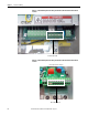
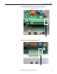
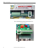
Control pan, to the left of the
HIM cradle.
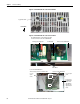
78 79 35 36 75 76