
User Manual

Rockwell Automation Publication 20P-UM001K-EN-P - July 2014 55
Installation and Wiring Chapter 1
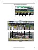
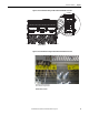
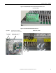
Figure 29 - Frame C Armature Voltage Feedback Circuit Terminal Block Location
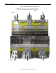
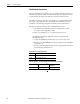
Figure 30 - Frame D Armature Voltage Feedback Circuit Terminal Block Location
1A1
(C)
A1 1A2
(D)
A2
1A1
(C)
A1 1A2
(D)
A2
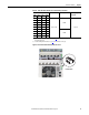
1A1
(C)
A1 1A2
(D)
A2
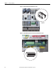
1A1
(C)
A1 1A2
(D)
A2
Bottom of Drive
Bottom of Drive, Left Side
Shown with terminals jumpered for
internal armature voltage feedback.