
User Manual

50 Rockwell Automation Publication 20P-UM001K-EN-P - July 2014
Chapter 1 Installation and Wiring
Armature Converter Connections
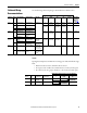
Table 11 - Armature and Safety Ground (PE) Terminal Specifications
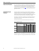
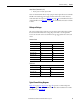
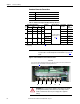
Figure 23 - Frame A Armature Converter Terminal Locations
Terminals Description
U, V, W Three phase AC input to the armature converter
C, D DC output to the motor armature
PE Safety ground
Frame
Drive Current Rating Code
(1)
Terminals Wire Size and Type Terminal Bolt
Size (mm)
Tightening
Torque
N•m (lb•in)
230V 460V 575 690
A 7P0…055 4P1…052 – – U, V, W, C, D, PE
See Cable and Wiring
Recommendations on
page 43
5 6 (53)
073…110 073…129 – – Terminal Block 12 (106)
B All All All – U, V, W, C, D 10 25 (221)
PE 8 15 (132.75)
C All All All All U, V, W, C, D 10 25 (221)
PE 8 15 (132.75)
D All All All All U, V, W, C, D, PE 12 45 (398.2)
(1) See Standard Drive Catalog Number Explanation on page 15, positions 8, 9 and 10 for corresponding drive HP rating, armature amp rating and
field amp rating.
IMPORTANT
Certain frame D drives require the use of a terminal adapter kit(s) for terminals
U, V, W, C and D. See Terminal Adapter Kits for Frame D Drives on page 264
for
details.
UCV DWPE
Front View
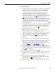
ATTENTION: Do not operate the drive with the power terminal cover removed.
Operating the drive with the power terminal cover removed may result in a
hazardous condition that could cause personal injury and/or equipment
damage.
Note: Front view of drive shown with bottom protective and power terminal covers removed. See Remove the
Drive Covers on page 27
for information on removing the drive covers.