
User Manual

Rockwell Automation Publication 20P-UM001K-EN-P - July 2014 49
Installation and Wiring Chapter 1
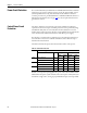
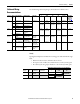
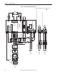
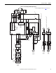
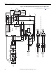
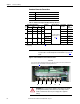
Power Wiring Diagrams Notes
1. For frame B and C drives only, a jumper is required between terminals SA
and SB for 115V AC control input power. See Control Circuit Input
Power on page Control Circuit Input Power for more information.
2. An Isolation Transformer and/or 3…5% impedance Line Reactor is
required. If the Isolation Transformer provides the required 3…5%
impedance, a Line Reactor is not required. See AC Input Line Reactors
and AC Input Contactors on page 254
and Isolation Transformers on page
256
for recommendations. It is recommended that the isolation
transformer has a grounded Wye secondary neutral. If the PowerFlex DC
drive is installed in a system with an ungrounded Wye neutral or with an
impedance ground connection, see Grounding for Installations in an
Ungrounded or High-Impedance, Neutral Ground, or System on page 34
for more information.
3. AC input fuses for the armature converter are customer supplied for frame
A and B drives and are internally mounted on frame C and D drives. See
Drive Power Circuit Protection on page 236
for fuse recommendations.
4. Par 140 [Digital In8 Sel] set to 31 “Contactor.”
5. If the +24V internal power supply is used, terminal 18 (24V common)
must be jumpered to terminal 35 (digital input common).
6. Customer supplied armature output fuses are required on four quadrant
and are recommended on two quadrant Frame A and B drives. See Drive
Power Circuit Protection on page 236
for fuse recommendations.
7. Optional armature voltage feedback sensing not required with AC
contactor.
8. The “Enable” input must be removed to perform a dynamic braking stop.
9. Par 1391 [ContactorControl] = 1 “AC Cntctr” and Par 1392 [Relay Out
1 Sel] = 25 “Contactor”. Important: Terminal 35 and 36 are on the
Control Power / Relay Outputs Terminal block, NOT the I/O terminal
blocks. See Figure 37
on page 63…Figure 41 on page 65.
10. Only frame C and D drives require an external power supply for the
heatsink cooling fan(s). See Frame C Heatsink Cooling Fan Specifications
on page 69
and Frame D, Series B Heatsink Cooling Fan Specifications on
page 71
for more information.
11. See Field Converter Connections on page 56
.
12. If sourced from the main 3 phase AC input, the connections must be taken
from the primary side of the isolation transformer or line reactor (clean
power).
13. Fuses or a circuit breaker. See Frame C Heatsink Cooling Fan
Specifications on page 69
and Frame D, Series B Heatsink Cooling Fan
Specifications on page 71
for detailed information.
14. For frames B, C, and D drives, a pilot relay is required for the contactor
coil.