
User Manual

46 Rockwell Automation Publication 20P-UM001K-EN-P - July 2014
Chapter 1 Installation and Wiring
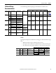
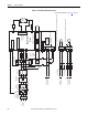
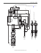
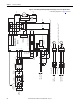
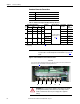
Figure 20 - Power Wiring with AC Input Contactor
M
C
D
Aux
PowerFlex DC
Drive
36
(9)
34
(4)
(on I/O TB4)
19
(5)
(+24V on I/O TB2)
(N.O. Relay)
M1 AC Contactor
Control
Board P/S
115V or 230V AC
Input Source
(1, 12)
V2
U2
F2
A1
A2
35
(9)
U
V
W
3 Phase
AC line
L1
L2
L3
13 14
L1
L2
L3
A1
T1
T2
T3
A2
U1
V1
C1
D1
F1
FS2
(6)
FS2
(6)
FS1
(3)
FS1
(3)
FS1
(3)
FU1
FV1
Field Power Terminal Block
Control Power / Relay Outputs
Terminal Block
A1
A2
Armature Volt.
Fdbk. Term. Blk.
(7)
1A1
1A2
Line Reactor
(2)
Isolation
Transformer
(2)
Lockable
Installation
Disconnect
SB
(1)
SA
(1)
PE
Safety Ground
AC Input
Voltage
460 VAC
Max. or
230 VAC
Min.
(11)
EMC Filter
(if used)
K1
(14)
K1
(14)
K1
(14)
Fan Power Terminal Block - Series B ,Frame D Drives Only
(10)
400...460V AC
Input Source
(12)
See footnote
(13)
FU
FU
FU
U3
V3
W3
Fan Power Terminal Block - Frame C and Series A, Frame D Drives Only
(10)
230V AC
Input Source
(12)
See footnote
(13)
FU
FU
U3
V3
See Power Wiring Diagrams Notes on page 49 for footnotes.