
User Manual

Rockwell Automation Publication 20P-UM001K-EN-P - July 2014 45
Installation and Wiring Chapter 1
Control Circuit (Terminals U2, V2)
• 115V ±15% or 230V ±15%, 1Ph
Note: For frame B and C drives only, a jumper must be placed between terminals
SA-SB on the switching power supply circuit board for the control circuits to
work with 115V AC input. See Figure 47
on page 68 for terminal block location
on frame B drives and Figure 48
on page 68 for terminal block location on frame
C drives.
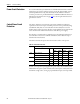
DC Output Voltages
The output voltages below take into account an AC input undervoltage within
the stated tolerance limits and a voltage drop of 4% due to an AC input line
reactor. It is the same as the rated armature voltage suggested for the connected
motor.
Armature Circuit
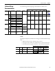
Field Circuit
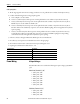
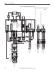
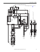
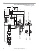
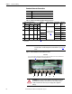
Typical Power Wiring Diagrams
Figure 20 on page 46…Figure 22 on page 48 represent recommended power
wiring configurations for standard PowerFlex DC drive installations. For SAR
installations, see Appendix H
.
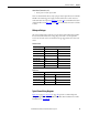
AC Input Voltage DC Output Armature Voltage (Terminals C & D)
(Terminals U, V, W) Two Quadrant Drive Four Quadrant Drive
230V ±10%, 3Ph 260V 240V
400V ±10%, 3Ph 470V 420V
440V ±10%, 3Ph 530V 460V
460V ±10%, 3Ph 560V 480V
480V ±10%, 3Ph 580V 500V
575V ±10%, 3Ph 680V 600V
690V ±10%, 3Ph 810V 720V
AC Input Voltage DC Output Field Voltage
(1)
(Terminals C1 & D1)
(1) The max field voltage is equal to 0.85 x AC input line voltage
(Terminals U1 & V1) Fixed Field Adjustable Field
230V ±10%, 1Ph 200V 200V
400V ±10%, 1Ph 310V 310V
460V ±10%, 1Ph 360V 360V