
User Manual

376 Rockwell Automation Publication 20P-UM001K-EN-P - July 2014
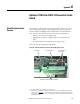
Appendix G Optional 115V AC to 24V DC I/O Converter Circuit Board
I/O Converter Board Wiring
Table 92 - Recommended Signal Wire Size
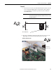
A 75 x 2.5 x 0.4 mm (3.0 x 0.1 x 0.02 in.) flathead screwdriver is recommended
for connecting wire to the terminal block inputs. Strip the ends of the cables to a
length of 6.5 mm (0.26 in.).
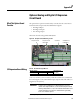
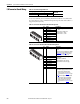
Table 93 - I/O Converter Board M_IN Terminal Block Designations
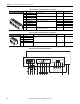
Table 94 - I/O Converter Board M_OUT Terminal Block Designations
Wire Type and Size Tightening Torque
N•m (lb•in)
Flexible (mm
2
)multi-core (mm
2
)AWG
0.14…1.5 0.14…1.5 28…16 0.4 (3.5)
No. Signal Description
1 Digital Input 1 Rated input voltage:115V AC ±10%
50…60Hz.
ON input voltage: 115V AC ±10%
OFF input voltage: 0 - 70V AC
ON input current: 4…5.5 mA
2 Digital Input 2
3 Digital Input 3
4 Digital Input 4
5 Digital Input 5
6 Digital Input 6
7 Digital Input 7
8 Digital Input 8
Com Digital Input Common
No. Signal Description
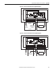
24V +24VDC Supply 24V DC ±10%, 40 mA power supply. Max. load
120 mA.
Supply power can be provided by the +24V DC
supply on the control board I/O (terminal 19 -
see Figure 105
on page 377) or an external
source (see Figure 106 on page 377).
1 Digital Output 1 Output type: Open collector, PNP type with 15
kΩ pull-down
Output current: 10 mA max.
Delay time hw OFF to ON: 5 ms (typ.)
Delay time hw ON to OFF: 50 ms (typ.)
2 Digital Output 2
3 Digital Output 3
4 Digital Output 4
5 Digital Output 5
6 Digital Output 6
7 Digital Output 7
8 Digital Output 8
0V 24V Common Common for the power supply.
· If an internal supply is used, this terminal
must be wired to the digital input
common (terminal 16 or 35) on the
control board I/O. See Figure 105
on page
377.
· If an external supply is used, this terminal
must be wired to the external 24V DC
supply common and the digital input
common (terminal 16 or 35) on the
control board I/O. See Figure 106
on page
377.
2
3
4
5
1
7
8
6
COM
1
2
3
4
24V
6
7
8
0V
5