
User Manual

374 Rockwell Automation Publication 20P-UM001K-EN-P - July 2014
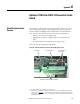
Appendix F Optional Analog and Digital I/O Expansion Circuit Board
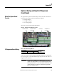
Table 90 - I/O Expansion Board Terminal Block 1 Designations
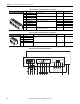
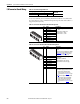
Table 91 - I/O Expansion Board Terminal Block 2 Designations
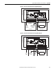
Figure 103 - I/O Expansion Board Wiring Diagram
No. Signal Description Factory Default Config. Parameter
1 Analog Output 3 (+) ±10V, 5 mA maximum 18 “Fld Current” 68 [Anlg Out3 Sel]
2 Analog Output 3 (–)
3 Analog Output 4 (+) ±10V, 5 mA maximum 14 “Motor Volts” 69 [Anlg Out4 Sel]
4 Analog Output 4 (–)
5 Digital Output Common – –
6 Digital Output 5 (+) Max volt. +30V, max cur. 50 mA 26 “Alarm” 149 [Digital Out5 Sel]
7 Digital Output 6 (+) – –
8 Digital Output 7 (+) – –
9 Digital Output 8 (+) – –
10 +24VDC Drive supplied power for Digital Outputs.
Max volt. +30V, max. cur. 80 mA.
––
2
3
4
5
1
7
8
9
10
6
No. Signal Description Factory Default Config. Parameter
11 Digital Input 9 Max volt. +30V, max cur. 15V/3.2 mA, 24V/5 mA, and 30V/
6.4 mA.
––
12 Digital Input 10
13 Digital Input 11
14 Digital Input 12
15 Digital Input Common – –
12
13
14
15
11
Analog Outputs
34
1 234
Digital Outputs
5678
5 6789 10
ylppuS
Digital Inputs
11 12 13 14 15
9
19 18
42V0
V42+
0V
+24V
Control Board
I/O Expansion Board
10 11 12