
User Manual

Rockwell Automation Publication 20P-UM001K-EN-P - July 2014 37
Installation and Wiring Chapter 1
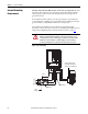
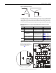
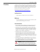
Figure 16 - Frame C Transient Noise Filter Circuit Board (FIL-31), 200V…500V AC Input Drives,
Ground Wire Location
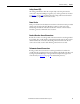
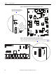
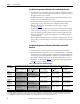
Figure 17 - Frame C Transient Noise Filter Circuit Board (FIL-57, FIL-69), 575V…690V AC Input
Drives, S1 Jumper Location
STS
PORT
MOD
NET A
NET B
U
V
C
Yellow/Green (ground) wire
Transient noise filter board
Note: Remove the front covers from the drive to access the transient noise filter circuit board. See page 28 for
instructions. The transient noise filter board is between terminals C and D below the control EMI shield.
S1
F1 F2 F3
P4 P3
S1
Note: Remove the front covers from the drive to access the transient noise filter circuit board. See page 28 for
instructions. The transient noise filter board is on the left side of the control EMI shield.