
User Manual

Rockwell Automation Publication 20P-UM001K-EN-P - July 2014 351
Control Block Diagrams Appendix D
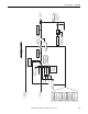
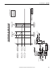
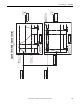
Torque Mode Selection
Torque Mode Selection
P40
Trim Torque
P39
Torque Ref
+
+
To Current Regulator
Block Diagram
P353
Zero Torque
P70
Anlg In1 Sel
P75
Anlg In2 Sel
P80
Anlg In3 Sel
P1323
DPI P1 Select
P1324
DPI P2 Select
P1325
DPI P3 Select
P1326
DPI P4 Select
P1327
DPI P5 Select
P14
Selected TorqRef
n
d
P500
Flux Ref Pct
P241
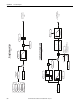
Spd Trq Mode Sel
MIN
MAX
+
+
P17
Motor Trq Ref
P463
Flux Filter BW
P462
Flux Divide
From Speed Regulator
Block Diagram
Zero Torque 0
0.00
Speed Reg 1
Torque Reg 2
SLAT Min 3
SLAT Max 4
Sum 5
1
Inertia Comp
Torque Ref
0
Active
Not Active
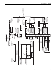
P382
Drive Status 2
b7 Forced Spd
b8 Speed Mode
b9 Torque Mode
0
1
P382
Drive Status 2
b7 Forced Spd
P15
SLAT Err Stpt
P16
SLAT Dwell Time
Σ
P17 [Motor Trq Ref] is divided
by the ux reference when
P462 [Flux Divide] is set to
0 “Torque Ref”.
(2 ms)
From Speed Regulator
Block Diagram
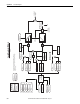
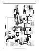
Inertia Compensation
Output
+
0
1.00
P782
PID Target
P1210
W Target