
User Manual

Rockwell Automation Publication 20P-UM001K-EN-P - July 2014 35
Installation and Wiring Chapter 1
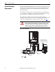
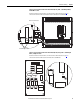
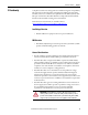
Figure 12 - High-impedance Ground
Grounding the Wye secondary neutral through a resistor is an acceptable method
of grounding. In this case, in a short-circuited secondary condition, none of the
output phases to ground will exceed the normal line to line voltage. The resistor
is often used to detect ground current by monitoring the associated voltage drop.
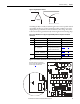
Table 8 - Drive Modifications to Support Ungrounded Wye Neutral or Impedance Grounded
Connections
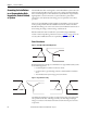
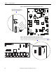
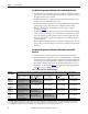
Figure 13 - Frame A Pulse Transformer Circuit Board S9 Jumper Location
Frame Circuit Board Jumper/Connection Figure to see for Details
A Pulse transformer (FIR1-xx-xx) Remove jumper S9 Figure 13
on page 35
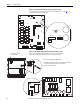
B Pulse transformer (FIR2-xx-xx) Remove jumper S9 Figure 14 on page 36
C Pulse transformer (FIR3-xx-xx) Remove jumper S9 Figure 15 on page 36
Transient noise filter (FIL-31),
200V…500V AC drives
Disconnect the filter board yellow/
green (ground) wire from the PE
connection on the drive chassis
Figure 16 on page 37
Transient noise filter (FIL-57,
FIL-69), 575V…690V AC drives
Remove jumper S1 Figure 17 on page 37
D Pulse transformer (FIR-D-xx-xx) Remove capacitors C121 and C122 Figure 18 on page 38
Overvoltage clipping (CFSF-xxx) Remove jumper S1 Figure 19 on page 38
S9
T01 T04 T02 T05
T03
T06
T1 T4 T2 T5 T3 T6
78 79 35 36 75 76 U2 V2
S4
S3
XY
XR
TR2 TR1
XP
XSW
XSW1
X3
X4
S9
Note: Remove the front covers from the
drive to access the pulse transformer circuit
board. See page 27
for instructions.