
User Manual

298 Rockwell Automation Publication 20P-UM001K-EN-P - July 2014
Appendix C Application Notes
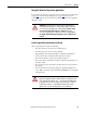
Speed Reference Setup
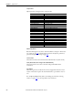
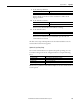
1. Set the minimum speed.
2. Set the maximum speed limits.
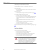
3. Set the digital input functions.
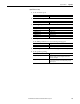
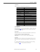
4. Set the speed reference.
Set the DPI Speed Reference to the nominal operating speed.
5. Verify the speed reference in parameter 1329 [Speed Ref Source] = 1323.
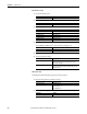
6. Set the speed loop tuning.
Torque Prove Setup
Carefully perform the following steps in the order presented.
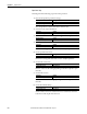
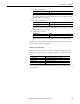
1. Enter the Torque Prove parameter settings.
2. Select the source of speed feedback.
Parameter Setting
1 [Minimum Speed] 0.00
Parameter Setting
2 [Maximum Speed] Speed limit used during normal operation
Parameter Setting
133 [Digital In1 Sel] “Stop/CF” (2)
134 [Digital In2 Sel] “Run Forward” (6)
135 [Digital In3 Sel] “Run Reverse” (7)
136 [Digital In4 Sel] “Enable” (1)
137 [Digital In5 Sel] “Flt MicroPsn” (65)
138 [Digital In6 Sel] “Not Used” (0)
Parameter Setting
70 [Anlg In1 Sel] “Off” (0)
323 [DPI P1 Select] “Speed Ref A” (1)
Parameter Setting
434 [Speed Reg BW] 20 R/S
Defines the reactivity of the speed regulator. This is used to
calculate Kp and Ki gains.
433 [Total Inertia] 1.5 Secs
This value can be increased or decreased depending on Speed
regulator response.
Parameter Setting
629 [Relay Out 2 Sel] “TP Brake Cmd” (31)
1100 [Torq Prove Cfg] Bit 0 “TP Enable” = 1
Bit 1 “Encoderless” = 1
Bit 5 “BrkSlipEncls” = 1
Parameter Setting
414 [Fdbk Device Type] “DC Tach” (2)