
User Manual

296 Rockwell Automation Publication 20P-UM001K-EN-P - July 2014
Appendix C Application Notes
Troubleshooting Crane Setup with Encoder/Resolver Feedback
The following faults commonly occur during drive commissioning.
F4 “AC Undervoltage”
• If the mains supply is still present, reduce the undervoltage level at P481
[UnderVolt Thresh].
F5 “Arm Overvoltage”
• Verify the parameter settings as stated in Set Up the Drive on page 292
.
F94 “TrqProve Spd Band” (Speed deviation fault)
• This fault is only active when TorqProve is enabled.
• The speed loop tuning is incorrect. Increase P434 [Spd Reg BW] or P433
[Total Inertia]. If theses values are too high the regulator will become
unstable.
• P1008 [Spd Reg Fdbk] should follow P113 [Ramp Out] as closely as
possible.
• The drive is going into current limit. The drive is undersized or
acceleration / deceleration is set too fast.
• The brake is not opening. Check for faulty brake operation.
For more fault information, refer to Chapter 4 Troubleshooting, starting on page
215
.
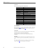
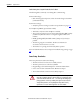
Crane Setup - Encoderless
These setup instructions assume the following.
• The drive and motor size have been carefully selected
• The drive parameters are at the factory defaults
• Programming is done with DriveExplorer or DriveTools SP software
• Crane control is done via Run Forward / Run Reverse inputs
• The mechanical brake control is wired to Relay Output 2
ATTENTION: Loss of control in suspended load applications can cause personal
injury and/or equipment damage. Loads must always be controlled by the drive
or a mechanical brake. Parameters 1100…1114 are designed for lifting/torque
proving applications. It is the responsibility of the engineer and/or end user to
configure drive parameters, test any lifting functionality and meet safety
requirements in accordance with all applicable codes and standards.