
User Manual

294 Rockwell Automation Publication 20P-UM001K-EN-P - July 2014
Appendix C Application Notes
Torque Prove Setup
Carefully perform the following steps in the order presented.
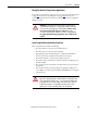
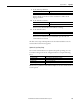
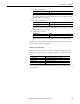
1. Enter the Torque Prove parameter settings.
Once Torque Prove is activated the drive is in alarm state.
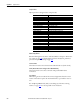
2. Select the source of speed feedback.
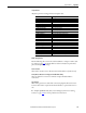
3. Set the time to decrease motor torque during the Brake Slip test.
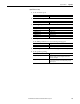
4. Set the speed deviation.
Increase this setting if the drive faults on F94 “TorqPrv Spd Band.”
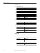
5. Set the speed deviation level.
Increase this setting if the drive faults on F94 “TorqPrv Spd Band.”
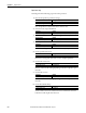
6. Set the brake release time.
Increase or decrease this setting depending on the time required to open
the brake.
7. Set the brake set time.
Increase or decrease this setting depending on the time required to close
the brake.
8. Set the allowable brake slip.
Sets the number of motor revolutions the motor is allowed to lower the
load when a brake slip has been detected.
Parameter Setting
629 [Relay Out 2 Sel] “TP Brake Cmd” (31)
1100 [Torq Prove Cfg] Bit 0 “TP Enable” = 1
Parameter Setting
414 [Fdbk Device Type] “Encoder” (1) - Verify that P169 [Encoder PPR] is set correctly.
Drive Parameter Setting
1104 [Torq Limit Slew] 10.000 Secs (Default)
Parameter Setting
1105 [Speed Dev Band] 52.50 RPM (Default)
Parameter Setting
1106 [SpdBand Intgrtr] 60 ms (Default)
Parameter Setting
1107 [Brk Release Time] 100 ms (Default)
Parameter Setting
1108 [Brk Set Time] 100 ms (Default)
Parameter Setting
1109 [Brk Alarm Travel] 1.00 (Default)