
User Manual


26 Rockwell Automation Publication 20P-UM001K-EN-P - July 2014
Chapter 1 Installation and Wiring
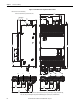
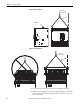
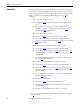
Figure 7 - Lift Frame C Drives
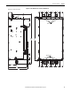
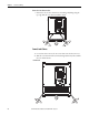
Figure 8 - Lift Frame D Drives
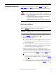
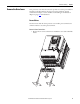
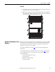
4. Lift the drive into place onto the bolts that are installed in the panel.
5. Install the remaining bolts into the panel. Tighten M8 bolts to a minimum
torque of 15 N
•m (132.7 lb•in) and M10 bolts to a minimum torque of 25
N
•m (221.2 lb•in).
Lifting flanges
Must be less
than 45° angle
Must be less
than 45° angle