
User Manual

Rockwell Automation Publication 20P-UM001K-EN-P - July 2014 259
Supplemental Drive Information Appendix A
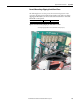
DC Contactor Crimp Lug Kit
Specifications
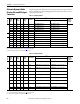
Use the information provided in the table below to assist you in ordering the
correct Lug kit for your application.
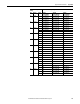
C 495 495 404.4 300 HUBBELL_Y101W595GB 500 0.8 ABB_EHDB520C2P-1L2S ABB_EHDB520C-1L22SS
(5)
667 667 544.9 400 HUBBELL_Y109W542GB 500 0.625 ABB_EHDB800C2P-1L2S ABB_EHDB800C-1L22SS
(5)
D 800 830 678.1 500
(1)
500 0.463 ABB_EHDB960C2P-1L2S ABB_EHDB960C-1L22SS
(5)
960 996 813.7 600
(2)
500 0.322 SIEMENS-MFG_14-193-
101-58-2 (Qty 2)
SIEMENS-MFG_14-193-
101-58-2 (Qty 1)
(5)
1K1 1162 949.4 700
(2)
500 0.322 SIEMENS-MFG_14-193-
101-58-2 (Qty 2)
SIEMENS-MFG_14-193-
101-58-2 (Qty 1)
(5)
1K3 1328 1085.0 800
(2)
500 0.255 CUTLER-
HAMMER_6702ED636-2
(Qty 2)
CUTLER-
HAMMER_6702ED636-2
(Qty 1)
(5)
1K4 1494 1220.6 900
(2)
500 0.255 CUTLER-
HAMMER_6702ED636-2
(Qty 2)
CUTLER-
HAMMER_6702ED636-2
(Qty 1)
(5)
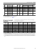
(1) No Dynamic Brake Resistor kit available for this drive rating - must be sourced locally.
(2) Coil voltage = 115V AC, 50/60Hz.
(3) See DC Contactor Crimp Lug Kit Specifications on page 259
for more information.
(4) Wire and Lug size dependant on enclosure dimensions and local codes.
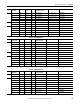
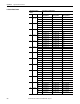
Frame
Drive Current
Rating Code
DC
Amps
AC Line
Amps
Hp Dynamic Brake Resistor
Kit Cat. No.
Armature
Voltage
(Volts)
Total DB
Resistance
(ohms)
DC Loop Contactor Cat. No.
(2)
DC Contactor
Crimp Lugs
Cat. No.
(3)
Drive without Dynamic
Brake
Drive with Dynamic
Brake
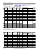
Rated Motor Armature
Current
(1)
A DC
DC Contactor Rating
A DC
Armature Conductor Size
(2)
AWG
DB Conductor Size
(3)
AWG
Armature Conductor
Crimp Lug Hole Size
DB Conductor Crimp
Lug Hole Size
Lug Kit Catalog
Number
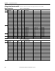
4.1…35 56 8 8 #10 #10 1370-LG40
45…52 56 6 8 #10 #10 1370-LG52
55 56 4 8 #10 #10 1370-LG56
60…86 110 2 6 0.25 in. 0.25 in. 1370-LG92
100…110 110 1/0 4 0.25 in. 0.25 in. 1370-LG110
129 180 2/0 2 0.3125 in. 0.3125 in. 1370-LG140
146 180 3/0 2 0.3125 in. 0.3125 in. 1370-LG160
147…167 180 4/0 2 0.3125 in. 0.3125 in. 1370-LG180
207…218 280 300MCM 1/0 0.5 in. 0.375 in. 1370-LG228
250…265 280 400MCM 2/0 0.5 in. 0.375 in. 1370-LG268
266…280 280 500MCM 3/0 0.5 in. 0.375 in. 1370-LG280
(1) The Rated Motor Armature Current is taken directly from the motor nameplate or motor data. The current listed in this column is the maximum current allowed for the Armature Conductor Size (column
3) and the DC Contactor Rating (column 2).
(2) The armature conductors are sized by multiplying the Rated Motor Armature Current by 1.25 as provided for in NEC 420-22 (1987). The DC lug ratings are determined from NEC Table 310-16 (1987) for
copper conductors, insulation temperature rated at 75° C (167° F) at an ambient temperature of 30° C (86° F). If conditions are other than shown in NEC Table 310-16, then refer to application codes.
(3) The dynamic braking (DB) conductors are sized as in footnote 2 above, but at half ampacity due to the short time duration of current flow in these conductors, and has been sized to satisfy NEMA Standard
ICS 3-302.62 - Dynamic Braking. If the load inertia is larger than that of the motor, calculations must be made to determine correct conductor sizing and DB resistor wattage per NEMA Standard ICS 3-
302.62.