
User Manual

250 Rockwell Automation Publication 20P-UM001K-EN-P - July 2014
Appendix A Supplemental Drive Information
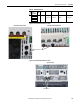
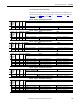
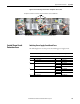
Figure 77 - Frame A Switching Power Supply Circuit Board Fuse Location
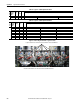
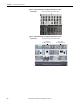
Figure 78 - Frame B Switching Power Supply Circuit Board Fuse Location
Top View of Drive
switching power supply circuit board fuse holder.
Top View of Drive
F1 = 3.15 A fuse
Rev. “H” and below only.
F2 = 2.5 A fuse
Rev. “H” and below only.
switching power supply circuit board fuse holders.