
User Manual


Rockwell Automation Publication 20P-UM001K-EN-P - July 2014 227
Troubleshooting Chapter 4
Common Drive Symptoms
and Corrective Actions
The following tables contain descriptions of common drive symptoms and the
possible solutions to correcting the problem.
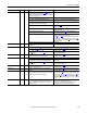
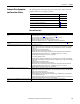
Drive will not start
If the drive is experiencing this problem See page
Drive will not start 227
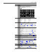
Drive starts but motor does not turn and no armature current 228
The motor does not reach commanded speed 228
The motor is turning in the wrong direction 228
The motor reaches maximum speed immediately 229
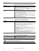
Drive Symptom Action
An external “Start” command was issued, but the drive does not
start.
• Verify that no faults or alarms are displayed. If a fault or alarm is displayed, follow the corrective action provided
(see Fault Descriptions on page 218
or Alarm Descriptions on page 224).
• The external wiring to the programmed Start terminal block connection is missing.
• Verify that +24V DC is present at terminal block connection.
• Verify that 24V Supply Common is connected between terminals 18 and 16.
• Verify that the configuration for Pars 133…144 [Digital Inx Sel] matches the switch wiring.
The drive is not in a "Ready" state, is not “Enabled” or a “Stop” is
asserted.
Check the Enable and Stop inputs. Verify that the wiring is correct (see I/O Wiring Examples on page 83
).
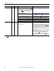
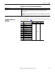
External AC Input or DC Output contactor, if used, has not closed. If using an AC Input contactor:
• Verify that the drive is "Ready", then verify that the required coil voltage is present at terminals 35 and 36 (Relay
Output 1). If the coil voltage is present at terminals 35 or 36, then verify that proper voltage is at the AC Input
contactor coil.
• Inspect the contactor for mechanical problems.
• Verify that Par 1391 [ContactorControl] is set properly.
• Verify that the contactor and/or auxiliary contact is properly wired to a digital input on the drive and that the
appropriate digital input selection parameter (133…144 [Digital Inx Sel]) is set to 31 “Contactor”.
• Verify that parameter 1392 [Relay Out 1 Sel] is set to 25 “Contactor”.
If using an external DC Output contactor:
• Verify that the drive is "Ready", then verify that the required coil voltage is present at terminals 35 and 36 (Relay
Output 1). If the coil voltage is present at terminals 35 or 36, then verify that the proper voltage is at the DC Output
contactor coil.
• Inspect the contactor for mechanical problems.
• Verify that parameter 1391 [ContactorControl] is set properly.
• Verify that the contactor and/or auxiliary contact is properly wired to a digital input on the drive and that the
appropriate digital input selection parameter (133…144 [Digital Inx Sel]) is set to 31 “Contactor”.
• Verify that parameter 1392 [Relay Out 1 Sel] is set to 25 “Contactor”.
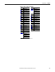
The external DB resistor contactor, if used, has not closed. • Verify that the drive is "Ready", then verify that the required coil voltage is present at terminals 75 and 76 (Relay
Output 2). If the coil voltage is present at terminals 75 or 76, then verify that proper voltage is at the DB contactor
coil.
• Inspect contactor for mechanical problems.
• Verify that parameter 1391 [ContactorControl] is set properly.
• Verify that the auxiliary contacts for the AC Input or DC Output contactor and DB contactor are properly wired in
series to a digital input on the drive.
• Verify that the appropriate digital input selection parameter (133…144 [Digital Inx Sel]) is set to 31 “Contactor”.
• Verify that parameter 629 [Relay Out 2 Sel] is set to 24 “ContactorDB”.
The drive starts from the HIM but will not start from the terminal
block.
Check masks for Terminal Block control (see parameters 591 [Logic Mask] and 592 [Start Mask]).