
User Manual

220 Rockwell Automation Publication 20P-UM001K-EN-P - July 2014
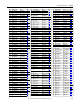
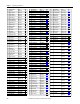
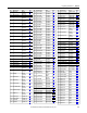
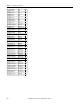
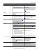
Chapter 4 Troubleshooting
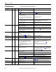
Overspeed 25 2 The encoder or tachometer feedback indicated a speed that is
more than the value of Par 585
[Overspeed Val].
Remove the excessive load or overhauling conditions or increase the
value of Par 585 [Overspeed Val].
Note: Configurable with Par 585 [Overspeed Val].
Params Defaulted 48 2 User parameters have been reset to their default values. Informational only.
Port 1-5 Adapter 71…75 2 The communication card has a fault. Check the DPI device event queue and corresponding fault
information for the device.
Port 1-5 DPI Loss 81…85 2 The DPI port stopped communicating. 1. Check the HIM connection.
2. If adapter was not intentionally disconnected, check the wiring
to the port. Replace the wiring, port expander, adapters, control
board or complete drive as required.
3. If an adapter was intentionally disconnected and the bit for that
adapter in Par 591
[Logic Mask] is set to “1”, this fault will occur.
To disable this fault, set the appropriate bit in [Logic Mask] for
the adapter to “0.”
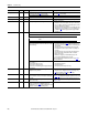
Power Failure 3 2 Possible causes include:
There is a fault in the 24V control board supply - the voltage is
below the permitted value. In most cases the cause is in the
external I/O wiring.
• Pull the plug-in I/O terminal blocks out of the control circuit
board and reset the drive via 1347
[Fault Clear]. If there are no
other faults, check the I/O wiring for a short-circuit including the
cable shielding.
• Check fuses F1 and F2 on the switching power supply circuit
board (frame A size drives only have one fuse - F1). Replace as
necessary.*
• Check varistor fuses F1, F2, and F3 on the pulse transformer or
Transient Noise Filter circuit boards for Frame C size drives.
Replace as necessary.*
• If this fault occurs again, an internal fault may be present.
Contact your Rockwell Automation sales office.
*Note: See Control Power Circuit Protection Fuses on page 249 for
fuse sizing information.
The incoming voltage to the control power terminals (U2, V2)
is too low due to:
• The AC input voltage is too low
• There are poor cable connections.
• The fuse(s) on the switching power supply circuit board
have blown.
• Verify AC input power level.
• Check all connections.
• Check and replace the fuse(s) if necessary.
Resolver Error 93 2 An error was detected with the resolver signal while it was
configured for use by the drive.
1. Verify the resolver wiring.
2. Verify the resolver configuration in Pars 423
[Reslvr Type Sel],
424 [Reslvr Spd Ratio], and 425 [Resolver Config].
3. Verify the resolver power supply.
Rev End Limit 96 2 A reverse direction end limit has been reached. When the end
limit is reached the contacts open and a drive current limit
stop occurs.
This fault is always enabled when assigned to a digital input (see
Pars 133
…144). If digital limits (hardware signals) are in use, verify
that the digital inputs are connected to normally closed contacts.
Rev Over Travel 98 2 A reverse direction over travel signal has occurred, causing the
drive to coast to a stop.
This fault is always enabled when assigned to a digital input (see
Pars 133
…144).
Shorted SCR 89 2 A shorted SCR fault condition has been detected. This fault
can only occur when Par 213
[SCR Diag Test En], bit 1
“OpenSCR Tst” is set (= 1). The SCR (or SCR pair) that caused
the fault are shown in Par 214 [SCR Diag Status].
Replace failed SCR device(s).
Fault Name Number Type
(1)
Description/Possible Cause(s) Action(s)
IMPORTANT
Remove power from the drive before removing the I/O terminal blocks and/or
fuses.