
User Manual

Rockwell Automation Publication 20P-UM001K-EN-P - July 2014 195
Programming and Parameters Chapter 3
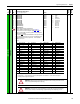
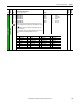
INPUT / OUTPUT
Digital Inputs
133
134
135
136
137
138
139
140
141
142
143
144
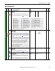
[Digital In1 Sel]
[Digital In2 Sel]
[Digital In3 Sel]
[Digital In4 Sel]
[Digital In5 Sel]
[Digital In6 Sel]
[Digital In7 Sel]
[Digital In8 Sel]
[Digital In9 Sel]*
[Digital In10 Sel]*
[Digital In11 Sel]*
[Digital In12 Sel]*
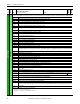
Selects the function driven by the digital input.
See Option Definitions for [Digital Inx Sel] on page 196
and 197.
*These parameters are used to configure the digital inputs on the I/O
Expansion circuit board. Do not use these parameters if the I/O Expansion
circuit board is not
installed.
Notes: Option 35 was changed from “Fld Weaken En” and option 64 “Invert
Flt” was added for firmware version 2.001. Option 34 “Field Reg En” was
changed for firmware version 3.001. Options 65…72 were added for
firmware version 6.001.
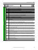
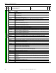
Options:
Default:
Default:
Default:
Default:
Default:
Default:
Default:
Default:
Default:
Default:
Default:
Default:
2 =
3 =
11 =
1 =
17 =
18 =
19 =
31 =
0 =
0 =
0 =
0 =
“Stop/CF”
“Start”
“Jog”
“Enable”
(1)
“Speed Sel 1”
“Speed Sel 2”
“Speed Sel 3”
“Contactor”
“Not Used”
“Not Used”
“Not Used”
“Not Used”
16-bit
Int
(1) A digital input (1…8 only) must be configured for “Enable”.
(2) For digital inputs 9…12, this option displays as “Reserved”, indicating that it is not available for use - do not select “Reserved” options.
(3) Not used for permanent magnet motor applications.
(4)
(5)
File
Group
No.
Parameter Name & Description
See page 114 for symbol descriptions
Values
Data Type
Related
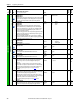
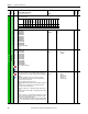
0 = “Not Used” (Off) 19 = “Speed Sel 3” 38 = “UsrDefinedA1” 57 = “Diam Preset0”
1 = “Enable”
(1)(2)
20 = “PI Enable” 39 = “UsrDefinedA2” 58 = “Diam Preset1”
2 = “Stop/CF”
(2)
21 = “PI Hold” 40 = “UsrDefinedA3” 59 = “Taper Enable”
3 = “Start”
(2)
22 = “PI Reset” 41 = “UsrDefinedA4” 60 = “Spd DemandEn”
4 = “Fwd/Reverse”
(2)
23 = “PI Invert” 42 = “UsrDefinedA5” 61 = “Winder Side”
5 = “Run”
(2)
24 = “Local” 43 = “UsrDefinedA6” 62 = “PI-PD Enable”
6 = “Run Forward”
(2)
25 = “Acc2 & Dec2” 44 = “UsrDefinedA7” 63 = “Jog TW En”
7 = “Run Reverse”
(2)
26 = “Accel 2” 45 = “Droop Enable” 64 = “Invert Flt”
8 = “Run Level”
(2)
27 = “Decel 2” 46 = “PD Enable” 65 = “Flt MicroPsn”
9 = “RunFwd Level”
(2)
28 = “MOP Inc” 47 = “PID SetptSel” 66 = “Fwd EndLimit”
10 = “RunRev Level”
(2)
29 = “MOP Dec” 48 = “PI Cent vs0” 67 = “Fwd DecLimit”
11 = “Jog”
(2)
30 = “Fast Stop” 49 = “PI Cent vs1” 68 = “Rev EndLimit”
12 = “Jog Forward”
(2)
31 = “Contactor”
(5)
50 = “Diam Calc” 69 = “Rev DecLimit”
13 = “Jog Reverse”
(2)
32 = “MOP Reset” 51 = “Diam Reset” 70 = “Fwd Ovr Trvl”
14 = “Aux Fault” 33 = “TorqueReduce” 52 = “DiamCalc Dis” 71 = “Rev Ovr Trvl”
15 = “Clear Faults” 34 = “Reserved” 53 = “Torq Wind En” 71 = “Lift Stop”
16 = “Auto/Manual” 35 = “Force MinFld”
(3)(4)
54 = “Speed Match”
17 = “Speed Sel 1” 36 = “Freeze Ramp” 55 = “Diam I/D En”
18 = “Speed Sel 2” 37 = “UsrDefinedA0” 56 = “Wind/Unwind”
ATTENTION: Enabling (forcing) the minimum field current while the drive is running could result in excessive
motor speed, equipment damage and/or bodily injury.
ATTENTION: Contactor status can only be used by the drive. Contactor status can not be used to initiate any
external action (for example, mechanical braking) or equipment damage and/or bodily injury can occur.