
User Manual

Rockwell Automation Publication 20P-UM001K-EN-P - July 2014 183
Programming and Parameters Chapter 3
UTILITY
Alarms
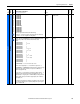
585 [Overspeed Val]
Speed value (rpm) at which an “Overspeed” fault (F25) will occur.
Notes: Typically set at 110% of Par 162 [Max Feedback Spd]. See Chapter 4 for a list
of fault and alarm descriptions. This parameter was added for firmware version
3.001.
Default:
Min/Max:
Units:
1925
0 / 7800
rpm
16-bit
Int
162
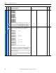
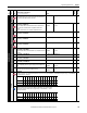
1380 [Drive Alarm 1]
Alarm conditions that currently exist in the drive. For each bit, 1 = condition true, and 0 = condition false.
Bit 0“DigInCflctA” - Digital input functions are in conflict.
Bit 1“DigInCflctB” - A digital Start input has been configured without a Stop input or other functions are in conflict.
Bit 2“DigInCflctC” - More than one physical input has been configured for the same input function.
Bit 3“BipolarCflct” - Parameter 1322 [Direction Mode] is set to “Bipolar” or “Reverse Dis” and one or more of the following digital input functions is
configured: “Fwd/Reverse,” “Run Forward,” “Run Reverse,” “Jog Forward” or “Jog Reverse.”
Bit 4“Ref Cflct” - Multiple speed or position references are configured.
Bit 5“CntactrCflct” - Contactor input functions are in conflict.
Bit 6“FB Cfg Cflct” - A speed feedback configuration error has occurred or is being provided by multiple sources.
Bit 7“Overvoltage” - There is an overvoltage on the armature circuit.
Bit 8“Over Temp” - The motor has exceeded its temperature rating [as signaled by the thermistor (PTC) or thermal switch connected to the drive
terminals 78 and 79].
Bit 9“Aux Input” - An auxiliary input interlock is open or a voltage (15…30 V) or reference signal is missing for the digital input set to 14 “Aux
Fault” (only updates if Par 354 [Aux Inp Flt Cfg] is set to 1 “Alarm”).
Bit 10“Field Loss” - The field current is too low.
Bit 11“SpdFdbk Loss” - The drive is not receiving a speed feedback signal.
Bit 12“PwrUp Start” - Indicates that the drive is starting or has automatically resumed running at commanded speed after drive input power was
restored.
Bit 13“Mtr Overload” - Indicates when the Motor Overload alarm level has been reached.
Bit 14“FldCfg Cflct” - Indicates a field configuration conflict.
Bit 15“Spd Fdbk Err” - Indicates an encoder or resolver error.
Notes: See Chapter 4 -Troubleshooting on page 215
for more information on faults/alarms. The name of bit 11 was changed from “Encoder Loss”
and bits 13 and 14 were added for firmware version 3.001. The name of bit 4 “AnalogCflct”, bit 6 “Encoder Cflct”, and bit 11 “Feedback Loss” were
changed and bit 15 was added for firmware version 5.002.
16-bit
Int
1322
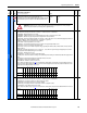
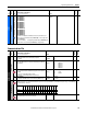
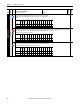
1394 [Drive Alarm 2]
Alarm conditions that currently exist in the drive. For each bit, 1 = condition true, and 0 = condition false.
Bit 0“BrakeSlipped” - The torque prove function encountered a brake slip condition.
Bit 1“TrqProvCflct” - The torque prove function is not properly configured.
Bit 2“TP Encls Cfg” - The torque prove function encountered an encoderless configuration conflict.
Bit 3“OpenSCR Trip” - An open SCR trip level has been reached.
Notes: See Chapter 4 -Troubleshooting on page 215
for more information on faults/alarms. This parameter was added for firmware version 6.001.
16-bit
Int
File
Group
No.
Parameter Name & Description
See page 114 for symbol descriptions
Values
Data Type
Related
A
ATTENTION: Verify that you have correctly set this parameter appropriately for your application. Incorrectly setting this
parameter may cause a hazard of personal injury and/or equipment damage.
Options
Spd Fdbk Err
FldCfg Cflct
Mtr Overload
PwrUp Start
SpdFdbk Loss
Field Loss
Aux Input
Over Temp
Overvoltage
FB Cfg Cflct
CntactrCflct
Ref Cflct
BipolarCflct
DigInCflctC
DigInCflctB
DigInCflctA
Default 0000000000000000
Bit 1514131211109 8 7 6 5 4 3 2 1 0
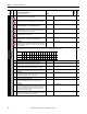
Options
Reserved
Reserved
Reserved
Reserved
Reserved
Reserved
Reserved
Reserved
Reserved
Reserved
Reserved
Reserved
OpenSCR Trip
TP Encls Cfg
TrqProvCfl ct
BrakeSlipped
Default xxxxxxxxxxxx0000
Bit 1514131211109 8 7 6 5 4 3 2 1 0