
User Manual

Rockwell Automation Publication 20P-UM001K-EN-P - July 2014 181
Programming and Parameters Chapter 3
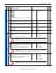
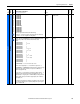
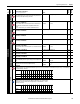
UTILITY
Faults
1361
1362
1363
1364
1365
1366
1367
1368
1369
1370
[Fault 1 Time]
[Fault 2 Time]
[Fault 3 Time]
[Fault 4 Time]
[Fault 5 Time]
[Fault 6 Time]
[Fault 7 Time]
[Fault 8 Time]
[Fault 9 Time]
[Fault 10 Time]
The time between initial drive power up and the occurrence of the associated trip
fault.
Default:
Min/Max:
Units:
Read Only
0.000 / 134000000.000
hr.
Real
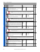
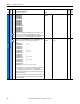
1371 [Fault Arm Amps]
Captures and displays the armature current (as a percentage of rated current) at
the time of the last fault.
Default:
Min/Max:
Units:
Read Only
–/+200
%
16-bit
Int
1372 [Fault Speed]
Captures and displays the output speed (rpm) of the drive at the time of the last
fault.
Default:
Min/Max:
Units:
Read Only
– / +8192
rpm
16-bit
Int
1373 [Fault Field Amps]
Captures and displays the field current (as a percentage of rated current) at the
time of the last fault.
Default:
Min/Max:
Units:
Read Only
0.00 / 100.00
%
Real
1374 [Fault Voltage]
Captures and displays the armature voltage at the time of the last fault.
Default:
Min/Max:
Units:
Read Only
- / + 999.00
Vdc
Real
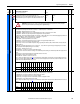
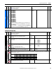
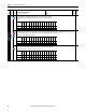
Alarms
203 [OverVolt Flt Cfg]
Determines the response of the drive to an overvoltage condition (F5 “Arm
Overvoltage”).
Note: See Chapter 4 for a list of alarm and fault descriptions.
Default:
Options:
2 =
0 =
1 =
2 =
“Fault”
“Ignore”
“Ala rm”
“Fault”
16-bit
Int
354 [Aux Inp Flt Cfg]
Determines the response of the drive to an external fault condition (F2 “Auxiliary
Input”), i.e., no voltage at the digital input terminal assigned to [Digital Inx Sel]
with a value of 14 “Aux Fault”.
Notes: See Chapter 4 for a list of alarm and fault descriptions. Option 3 was
changed from “Quick Stop” to “Fast Stop” for firmware version 2.001.
Default:
Options:
2 =
1 =
2 =
3 =
4 =
5 =
“Fault”
“Ala rm”
“Fault”
“Fast Stop”
“Normal Stop”
“CurrLim Stop”
16-bit
Int
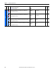
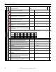
365 [OverTemp Flt Cfg]
Determines the response of the drive to a motor over temperature condition (F16
“Motor Over Temp”).
Notes: See Chapter 4 for a list of alarm and fault descriptions. Option 3 was
changed from “Quick Stop” for firmware version 2.001.
Default:
Options:
2 =
0 =
1 =
2 =
3 =
4 =
5 =
“Fault”
“Ignore”
“Ala rm”
“Fault”
“Fast Stop”
“Normal Stop”
“CurrLim Stop”
16-bit
Int
File
Group
No.
Parameter Name & Description
See page 114 for symbol descriptions
Values
Data Type
Related
A
A
ATTENTION: Setting this parameter to 0 “Ignore” or 1 “Alarm”, could result in motor and/or equipment damage. If set to
“Ignore” or “Alarm”, it is strongly recommended that an external means of protecting against this condition be provided.
A
ATTENTION: Setting this parameter to 1 “Alarm”, could result in motor and/or equipment damage. If set to “Alarm”, it is
strongly recommended that an external means of protecting against this condition be provided.
A
ATTENTION: Setting this parameter to 0 “Ignore” or 1 “Alarm”, could result in motor and/or equipment damage. If set to
“Ignore” or “Alarm”, it is strongly recommended that an external means of protecting against this condition be provided.