
User Manual

178 Rockwell Automation Publication 20P-UM001K-EN-P - July 2014
Chapter 3 Programming and Parameters
UTILITY
Diagnostics
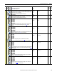
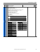
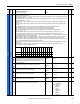
1328 [Drive Logic Rslt]
The final logic command resulting from the combination of all DPI and discrete inputs. This parameter has the same structure as the product specific logic
command received via DPI and is used in peer-to-peer communications. For each bit, 1=Condition true and 0=Condition false.
Bit 0 “Stop” - Stop command
Bit 1 “Start” - Start command
Bit 2 “Jog” - Jog command
Bit 3 “Clear Faults” - Clear faults command
Bit 4 “Forward” - Forward direction command
Bit 5 “Reverse” - Reverse direction command
Bit 6 “Local” - Local control command”
Bit 7 “MOP Inc” - MOP Increment command
Bit 8 “Accel 1” - Acceleration Rate 1 command
Bit 9 “Accel 2” - Acceleration Rate 2 command
Bit 10 “Decel 1” - Deceleration Rate 1 command
Bit 11 “Decel 2” - Deceleration Rate 2 command
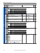
Bit 12…14 “Spd Ref ID 0”… “Spd Ref ID 2” - Speed reference source
(1)
Bit 15 “MOP Dec” - MOP Decrement command
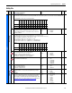
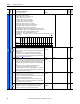
1329 [Speed Ref Source]
Displays the number of the parameter that is the source of the drive’s speed
reference (Par 118 [Speed Reg In]). For example, if the value of this parameter is
“70,” then Par 70 [Analog In 1] is the source of the speed reference value shown in
Par 118 [Speed Reg In].
Note: This parameter was added for firmware version 6.001.
Default:
Min/Max:
Read Only
0 / (highest possible parameter number)
16-bit
Int
118
File
Group
No.
Parameter Name & Description
See page 114 for symbol descriptions
Values
Data Type
Related
Options
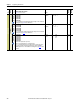
MOP Dec
Spd Ref ID 2
Spd Ref ID 1
Spd Ref ID 0
Decel 2
Decel 1
Accel 2
Accel 1
MOP Inc
Local
Reverse
Forward
Clear Faults
Jog
Start
Stop
Default 0000000000000001
Bit 1514131211109 8 7 6 5 4 3 2 1 0
(1)
Bits Description
14 13 12
000No Command - Manual Mode
001Spd Ref A Auto
010Spd Ref B Auto
011Preset Spd 3 Auto
100Preset Spd 4 Auto
101Preset Spd 5 Auto
110Preset Spd 6 Auto
111Preset Spd 7 Auto