
User Manual

Rockwell Automation Publication 20P-UM001K-EN-P - July 2014 17
Chapter 1
Installation and Wiring
This chapter provides information on how to mount and wire the PowerFlex DC
drive.
Most start-up difficulties are the result of incorrect wire connections. Take all
precautions to assure that wire connections are done as instructed. All items must
be read and understood before the actual installation begins.
For PowerFlex DC Stand-Alone Regulator (SAR) installations, see Appendix H
for important installation and configuration information. A 23PMDx catalog
number on the data nameplate on the drive identifies a SAR. (see Drive
Nameplate Data on page 12
for location).
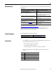
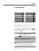
Topic Page Topic Page
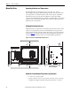
Mount the Drive 18 CE Conformity 39
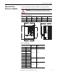
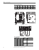
Approximate Drive Dimensions and
Weights
19 Power Circuit Protection 42
Lifting PowerFlex DC Drives 25 Control Power Circuit Protection 42
Remove the Drive Covers 27 Cable and Wiring Recommendations 43
Isolation Transformers / Line Reactors 29 Power Wiring 44
Contactors 30 DIP Switch and Jumper Settings 75
General Grounding Requirements 32 I/O Wiring 80
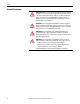
IMPORTANT
The PowerFlex DC drive is not designed for use with multiple motor
applications or resistive loads. Contact your Local Solution Center for multiple
motor applications. See Local Solution Centers, publication
DSDC-BR001
, for more information.
IMPORTANT
The recommended drive to motor horsepower ratio is 2:1.
ATTENTION: The following information is merely a guide for proper installation.
Rockwell Automation cannot assume responsibility for the compliance or the
noncompliance to any code, national, local or otherwise for the proper
installation of this drive or associated equipment. If codes are ignored during
installation, a hazard of personal injury and equipment damage exists.