
User Manual

164 Rockwell Automation Publication 20P-UM001K-EN-P - July 2014
Chapter 3 Programming and Parameters
APPLICATIONS
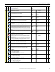
Diameter Calc
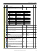
1204 [Line Spd Source]
Parameter number from which the line speed source for the winder function value
will be read.
Notes: Added options 0…47 for firmware version 4.001. Added option 48
“Resolver Spd” for firmware version 5.002.
Default: 0 = “Not Used” 16-bit
Int
Options:
1205 [Diam Inc Dec En]
This parameter It is used to improve system stability for winder/unwinder
applications. If this parameter is enabled and if applied to a winder, the calculated
diameter can never decrease; if applied to an unwinder, the calculated diameter
can never increase.
Default:
Options:
1 =
0 =
1 =
“Enabled”
“Disabled”
“Enabled”
16-bit
Int
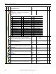
1206 [Diam Init Filter]
Initial filter on the diameter calculation.
Default:
Min/Max:
Units:
100
0 / 5000
ms
16-bit
Int
1207 [Diam Stdy Delay]
The amount of time during which the value of Par 1206 [Diam Init Filter] is kept
active after the value defined in Par 1155 [Line Spd Thresh] has been overcome.
Default:
Min/Max:
Units:
0
0 / 60000
ms
16-bit
Int
1155,
1206
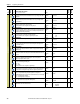
Winder Functions
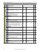
1171 [Variable J Comp]
Torque compensation due to the wound material as a percentage of the drive rated
current.
Default:
Min/Max:
Units:
0.00
0.00 / 199.99
%
Real
1172 [Constant J Comp]
Compensation of the fixed section (motor, reducer, pin) as a percentage of the drive
rated current.
Default:
Min/Max:
Units:
1.00
– / +100.00
%
Real
1173 [Materl Width Pct]
Width of the wound material as a percentage of the maximum width.
Default:
Min/Max:
Units:
100.00
0.00 / 100.00
%
Real
1174 [Static Friction]
Compensation for static friction as a percentage of the drive rated current.
Default:
Min/Max:
Units:
0.00
0.00 / 199.99
%
Real
1175 [Dynamic Friction]
Compensation for dynamic friction as a percentage of the drive rated current.
Default:
Min/Max:
Units:
0.00
0.00 / 199.99
%
Real
File
Group
No.
Parameter Name & Description
See page 114 for symbol descriptions
Values
Data Type
Related
A
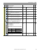
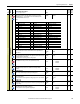
0 = “Not Used” 17 = “Max Fld Pct” (Par 467) 34 = “UsrDefined15” (Par 518)
1 = “Cur Lim Pos” (Par 8) 18 = “Fld Ref Pct” (Par 500) 35 = “Load Comp” (Par 698)
2 = “Cur Lim Neg” (Par 9) 19 = “UsrDefined0” (Par 503) 36 = “Out Volt Lvl” (Par 921)
3 = “CurLimPosOut” (Par 10) 20 = “UsrDefined1” (Par 504) 37 = “Filt Trq Cur” (Par 928)
4 = “CurLimNegOut” (Par 11) 21 = “UsrDefined2” (Par 505) 38 = “Speed Ratio” (Par 1017)
5 = “TrqRedCurLim” (Par 13) 22 = “UsrDefined3” (Par 506) 39 = “Spd Draw Out” (Par 1018)
6 = “Torque Ref” (Par 39) 23 = “UsrDefined4” (Par 507) 40 = “Roll Diam” (Par 1154)
7 = “Trim Torque” (Par 40) 24 = “UsrDefined5” (Par 508) 41 = “Tension Red” (Par 1179)
8 = “TorqueReg In” (Par 41) 25 = “UsrDefined6” (Par 509) 42 = “Torq Cur Pct” (Par 1193)
9 = “Trim Ramp” (Par 42) 26 = “UsrDefined7” (Par 510) 43 = “Ten Ref Pct” (Par 1194)
10 = “Trim Speed” (Par 43) 27 = “UsrDefined8” (Par 511) 44 = “CloseLp Comp” (Par 1208)
11 = “Ramp In” (Par 110) 28 = “UsrDefined9” (Par 512) 45 = “Actual Comp” (Par 1213)
12 = “Ramp Out” (Par 113) 29 = “UsrDefined10” (Par 513) 46 = “W Reference” (Par 1217)
13 = “Speed Reg In” (Par 118) 30 = “UsrDefined11” (Par 514) 47 = “Encoder Spd” (Par 420)
14 = “Adaptive Ref” (Par 183) 31 = “UsrDefined12” (Par 515) 48 = “Resolver Spd” (Par 428)
15 = “Arm Cur Pct” (Par 199) 32 = “UsrDefined13” (Par 516)
16 = “SpdRegOutPct” (Par 236) 33 = “UsrDefined14” (Par 517)
A
A
A
A
A
A
A
A