
User Manual

Rockwell Automation Publication 20P-UM001K-EN-P - July 2014 161
Programming and Parameters Chapter 3
APPLICATIONS
PID Control
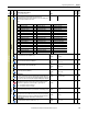
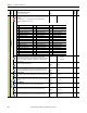
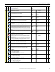
786 [PID Source]
Parameter number from which the PID source value will be read.
Notes: Added option 47 “Encoder Spd” for firmware version 4.001. Added option
48 “Resolver Spd” for firmware version 5.002.
Default: 0 “Not Used” 16-bit
Int
Options:
787 [PID Source Gain]
Gain of the input value to Par 786 [PID Source].
Default:
Min/Max:
1.00
–/+100.00
Real 786
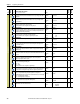
1046 [PID Accel Time]
Ramp acceleration time after the block PID offset.
Default:
Min/Max:
Units:
0.00
0.00 / 900.00
s
Real
1047 [PID Decel Time]
Ramp deceleration time after the block PID offset.
Default:
Min/Max:
Units:
0.00
0.00 / 900.00
s
Real
1254 [PID Error Gain]
Gain percentage of Par 759 [PID Error].
Default:
Min/Max:
Units:
1.005
0.000 / 32.005
%
Real 759
1258 [Enable PI PD]
Indicates the combined status of Par 769 [Enable PI] and 770 [Enable PD]. If both
Par 769 and Par 770 are enabled then Par 1258 [Enable PI PD] displays “Enabled”. If
either of Par 769 or Par 770 is disabled, Par 1258 [Enable PI PD] displays “Disabled”.
Default:
Min/Max:
Read Only
Disabled / Enabled
16-bit
Int
769,
770
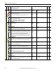
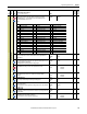
Init Diam Calc
794 [Diameter Calc]
Enables/Disables the diameter calculation function. If this parameter has been
programmed via a digital input, it must be brought to a logical high level.
• “0” = The diameter calculation is disabled.
• “1” = The diameter calculation is enabled.
Default:
Min/Max:
0
0 / 1
16-bit
Int
795 [DncrPosSpd]
Desired motor speed when the dancer is positioned in its central working position.
Default:
Min/Max:
0
–/+100
16-bit
Int
796 [Max Deviation]
A value, expressed in counts of D/A, that corresponds to the position of maximum
shift admitted by the dancer. This value is considered the starting measurement of
the dancer movement during the initial diameter calculation phase.
Default:
Min/Max:
8000
0 / 10000
16-bit
Int
797 [Gear Box Ratio]
Ratio reduction between the motor and the roll (< = 1).
Default:
Min/Max:
1.000
0.001 / 1.000
Real
File
Group
No.
Parameter Name & Description
See page 114 for symbol descriptions
Values
Data Type
Related
A
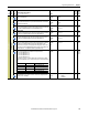
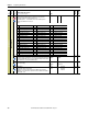
0 = “Not Used” 17 = “Max Fld Pct” (Par 467) 34 = “UsrDefined15” (Par 518)
1 = “Cur Lim Pos” (Par 8) 18 = “Fld Ref Pct” (Par 500) 35 = “Load Comp” (Par 698)
2 = “Cur Lim Neg” (Par 9) 19 = “UsrDefined0” (Par 503) 36 = “Out Volt Lvl” (Par 921)
3 = “CurLimPosOut” (Par 10) 20 = “UsrDefined1” (Par 504) 37 = “Filt Trq Cur” (Par 928)
4 = “CurLimNegOut” (Par 11) 21 = “UsrDefined2” (Par 505) 38 = “Speed Ratio” (Par 1017)
5 = “TrqRedCurLim” (Par 13) 22 = “UsrDefined3” (Par 506) 39 = “Spd Draw Out” (Par 1018)
6 = “Torque Ref” (Par 39) 23 = “UsrDefined4” (Par 507) 40 = “Roll Diam” (Par 1154)
7 = “Trim Torque” (Par 40) 24 = “UsrDefined5” (Par 508) 41 = “Tension Red” (Par 1179)
8 = “TorqueReg In” (Par 41) 25 = “UsrDefined6” (Par 509) 42 = “Torq Cur Pct” (Par 1193)
9 = “Trim Ramp” (Par 42) 26 = “UsrDefined7” (Par 510) 43 = “Ten Ref Pct” (Par 1194)
10 = “Trim Speed” (Par 43) 27 = “UsrDefined8” (Par 511) 44 = “CloseLp Comp” (Par 1208)
11 = “Ramp In” (Par 110) 28 = “UsrDefined9” (Par 512) 45 = “Actual Comp” (Par 1213)
12 = “Ramp Out” (Par 113) 29 = “UsrDefined10” (Par 513) 46 = “W Reference” (Par 1217)
13 = “Speed Reg In” (Par 118) 30 = “UsrDefined11” (Par 514) 47 = “Encoder Spd” (Par 420)
14 = “Adaptive Ref” (Par 183) 31 = “UsrDefined12” (Par 515) 48 = “Resolver Spd” (Par 428)
15 = “Arm Cur Pct” (Par 199) 32 = “UsrDefined13” (Par 516)
16 = “SpdRegOutPct” (Par 236) 33 = “UsrDefined14” (Par 517)
A
A
A
A
A
A
A
A
A