
User Manual

114 Rockwell Automation Publication 20P-UM001K-EN-P - July 2014
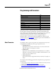
Chapter 3 Programming and Parameters
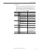
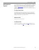
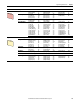
Parameters Table Example
12 3 4 5 6 7
File
Group
No.
Parameter Name & Description Values
Data Type
Related
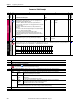
SPEED COMMAND
Speed Regulator
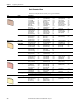
388 [Flying Start En]
Enables/Disables the ability of the drive to connect to a spinning motor at
actual rpm when a start command is issued.
• “Enabled” = When the drive is turned on, the speed of the motor is
measured and the ramp output is set accordingly. The drive then runs at the
set reference value.
• “Disabled” = When the drive is turned on, the ramp starts from zero.
Main uses:
• To connect to a motor that is already spinning due to its load (for example, in
the case of a pump, the flowing medium).
• Re–connection to a spinning motor after a fault or alarm.
Note: If the Flying Start function is disabled, be sure that the motor is not
spinning when the drive is turned on, or harsh motor deceleration in current
limit may occur.
Default:
Options:
0 =
0 =
1 =
“Disabled”
“Disabled”
“Enabled”
16-bit
Int
445 [Spd Up Gain Pct]
The Speed Up function gain as a percentage of Par 446 [Speed Up Base].
Default:
Min/Max:
Units:
0.00
0.00 / 100.00
%
Real
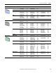
COMMUNICATIONS
Masks & Owners
591 [Logic Mask]
Determines which ports can control the drive when Par 1377 [Write Mask Act], bit 15 is set to “1.” If the bit for a port is set to “0,” the port will have no
control functions except for stop. 0 = Control Masked, 1 = Control Permitted, x = Reserved.
1377
A
A
Options
Reserved
Reserved
Reserved
Reserved
Reserved
Reserved
Reserved
Reserved
Reserved
Reserved
DPI Port 5
DPI Port 4
DPI Port 3
DPI Port 2
DPI Port 1
Digital In
Default xxxxxxxxxx000011
Bit 1514131211109 8 7 6 5 4 3 2 1 0
No. Description
1File – Lists the major parameter file category.
2Group – Lists the parameter group within a file.
3No. – Parameter number. = The parameter is only accessible when Par 211 [Param Access Lvl] = 1 “Advanced”.
= The parameter value cannot be changed until the drive is stopped.
4 Parameter Name & Description – Parameter name as it appears on an LCD HIM, with a brief description of the parameters function.
5Values – Defines the various operating characteristics of the parameter. Three types exist.
ENUM Default:
Options:
Lists the value assigned at the factory. “Read Only” indicates that the parameter is not configurable.
Displays the programming selections available.
Bit Options:
Default:
Bit:
Bit name.
Default setting.
Lists the bit place holder and definition for each bit.
Numeric Default:
Min/Max:
Units:
Lists the value assigned at the factory. “Read Only” indicates that the parameter is not configurable.
The range (lowest and highest setting) possible for the parameter.
Unit of measure and resolution as shown on the LCD HIM.
Important: Some parameters will have two unit values:
• For example: Analog inputs can be set for current or voltage as with Par 71 [Anlg Inx Config].
6Data Type - Identifies the parameter data type (i.e. integer, real).
7 Related – Lists parameters (if any) that interact with the selected parameter.
A