
User Manual

104 Rockwell Automation Publication 20P-UM001K-EN-P - July 2014
Chapter 2 Drive Start Up
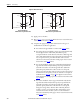
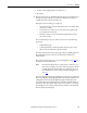
Figure 64 - Motor Connections
13. Apply power to the drive.
14. Repeat step 6
… step 9 on page 103. When the motor rotation direction
is correct, continue with step 15
.
15. Complete the appropriate procedure below based on the type of
feedback device used for the application:
❏ For armature voltage feedback - Continue with step 16
below.
❏ For analog tachometer feedback - Assert a Jog command and verify
that the sign and value of Par 1408 [Tachometer Speed]
corresponds with the actual direction of the motor. If the sign and
value of Par 1408 [Tachometer Speed] and the motor direction do
not correspond, remove power from the drive and reverse the
tachometer connections at the drive. Verify proper motor rotation
and continue with step 16
below.
❏ For encoder feedback - Assert a Jog command and verify that the
sign and value of Par 420 [Encoder Speed] correspond with the
actual direction of the motor. If the sign and value of [Par 420
[Encoder Speed] and the motor direction do not correspond,
remove power from the drive and reverse the encoder connections at
the drive. Reverse the polarity of only one channel, for example, B
and B NOT. See Tab l e 38
on page 86 for digital encoder terminal
block designations. Verify proper motor rotation and continue with
step 16
below.
❏ For resolver feedback - Assert a Jog command and verify that the
sign and value of Par 428 [Resolver Speed] correspond with the
actual direction of the motor. If the sign and value of Par 428
[Resolver Speed] and the motor direction do not correspond,
change the setting of bit 5 “Resolver Dir” in Par 425 [Resolver
Config], or remove power from the drive and verify the correct
resolver connections to the drive (refer to resolver installation
instructions for details). Verify proper motor rotation and continue
with step 16
below.
C1 (+)
C (+)
D (-)
D1 (-)
PowerFlex DC Motor
F1 (+)
A1
A2
F2 (-)
(2)
(2)
C1 (+)
C (+)
D (-)
D1 (-)
PowerFlex DC Motor
F1 (+)
A1
A2
F2 (-)
(2)
(2)
Straight Shunt Machine,
CCW Rotation Facing Commutator End
Straight Shunt Machine,
CW Rotation Facing Commutator End