
Owner manual

Rockwell Automation Publication 23P-IN001A-EN-P - June 2011 5
Step 4: Remove the
Power Interface
Circuit Board
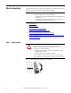
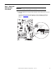
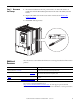
1. Record the DIP switch settings for SW3 and SW4, and the jumper pin locations for
J4 and J5.
See the PowerFlex DC Stand-Alone Regulator and Gate Amplifier User Manual,
publication 23P-UM001
, for more information about these DIP switches and
jumpers.
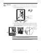
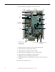
IMPORTANT
The power interface circuit board and the switching power supply circuit
board are removed together, as an assembly.
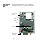
SW3 SW4
J5 J4
0VI RCT
XCT
MSB
LSB
ON
Off
On
Burden Resistor
Jumpers
External Burden Resistor
Terminal Block (XCT)
Binary Gain Amp
DIP Switches