
Owner manual
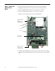
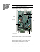
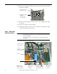
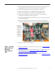
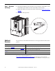
Table Of Contents
- PowerFlex DC Stand-Alone Regulator (SAR)Field Circuit Board Installation Instructions
- What This Kit Includes
- Tools That You Need
- What You Need to Do
- Step 1: Remove Power
- Step 2: Remove the Covers
- Step 3: Remove the Control Circuit Board
- Step 4: Remove the Power Interface Circuit Board and Switching Power Supply Circuit Board
- Step 5: Remove the Field Circuit Board
- Step 6: Install the New Field Circuit Board and Reassemble the SAR
- Step 7: Document the Change
- Additional Resources
- Back Cover
Rockwell Automation Publication 23P-IN003A-EN-P - June 2011 5
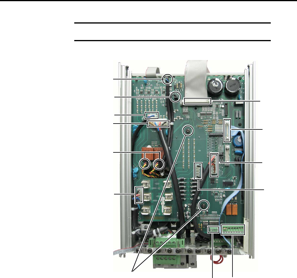
Step 4: Remove the
Power Interface
Circuit Board and
Switching Power
Supply Circuit
Board
1. Label and disconnect the plugs at connectors X3 and X4.
2. Label and disconnect the plugs at connectors XCD and XCD_IO.
3. Label and disconnect the ribbon cable at XPT1.
4. Label and disconnect the plugs at TH-CT and XF.
5. Label and disconnect the plugs at connectors at XP1 and XP2.
6. Label and disconnect the plug from connector XUVW.
7. Unplug the control power and relay terminal block.
8. Label and disconnect any external burden resistor circuit wires from the XCT
terminal.
9. Remove the mounting screws (2), and save for reassembly.
IMPORTANT
The power interface circuit board and the switching power supply circuit
board are removed together, as an assembly.
X3
X4
XCD
XCD_IO
XPT1
TH-CT
XF
XP1 and XP2
(respectively)
XUVW
Control Power and Relay
Terminal Block
XCT Terminal
Mounting Screws (2)
Tightening torque:
1.0 N•m (8.9 lb•in)
XR