
Manual

8 Rockwell Automation Publication 23P-IN009A-EN-P - June 2011
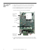
Step 6: Install the
New Discharge
Resistor and
Reassemble the
SAR
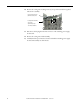
1. Strip about 5 mm (0.2 in.) from the end of the 1.3 mm
2
(16 AWG) wire insulation.
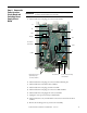
2. Solder the wires to the new discharge resistor wire terminals.
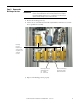
3. Mount the new discharge resistor to the heatsink.
4. Install the power interface circuit board and switching power supply circuit board in
reverse order of removal. See Remove the Power Interface Circuit Board and
Switching Power Supply Circuit Board on page 5.
5. Install the control circuit board in reverse order of removal. See Remove the Control
Circuit Board on page 4.
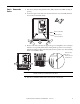
Step 7: Document
the Change
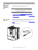
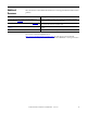
1. Record the installation of the new discharge resistor and date of installation on the
field installed option label on the side of the SAR (as shown below).
2. Replace the SAR covers in the reverse order of removal. See Remove the Covers
on page 3.
3. Install DPI cable (if present).
IMPORTANT
Thermal grease must be applied to the bottom of the discharge resistor
before securing it to the heatsink. Clean the surface of the heatsink and
the new discharge resistor with isopropyl alcohol, then apply a thin coat
of thermal grease to the discharge resistor.