
User Manual

8 Rockwell Automation Publication 23P-IN005A-EN-P - June 2011
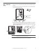
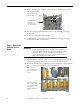
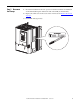
6. Pull the bottom air flow plate away from the chassis and remove the hidden capacitor
circuit board mounting screw (1).
7. Dispose of the capacitor circuit board and capacitors properly.
Step 6: Install the
New Capacitor
Circuit Board and
Reassemble the
SAR
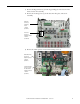
1. Install the new capacitor circuit board in reverse order of removal. See Remove the
Capacitor Circuit Board on page 6
2. Be sure about 5 mm (0.2 in.) of insulation is stripped from the end of the 1.3 mm
2
(16 AWG) wire leads.
3. Solder the capacitor circuit board wires to the respective in-rush limiting resistor and
discharge resistor terminals.
4. Install the power interface circuit board and switching power supply circuit board in
reverse order of removal. See Remove the Power Interface Circuit Board and
Switching Power Supply Circuit Board on page 5.
5. Install the control circuit board in reverse order of removal. See Remove the Control
Circuit Board on page 4.
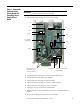
Hidden Mounting
Screw (1)
Tightening torque:
1.0 N•m
(8.9 lb•in)