
Owner's manual

68 Rockwell Automation Publication 23P-UM001D-EN-P - July 2012
Chapter 5 Power Interface and SCR Firing Order
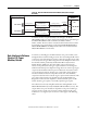
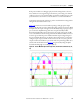
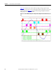
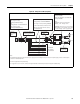
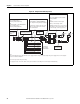
Figure 32 below shows an actual oscilloscope image of the gate pulse output
relative to the AC Line, L1 to L3, with negative phase rotation (L3, L2, L1). The
waveform shown in Figure 32
was generated by using the Alpha Test with the
firing angle set at 5 Degrees (full on).
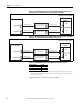
Figure 32 - Power Module Thyristor Firing Pattern, Negative Phase Rotation (L3, L2,
L1)