
Owner's manual

Rockwell Automation Publication 23P-UM001D-EN-P - July 2012 53
Gate Amplifier Installation and Wiring Chapter 3
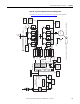
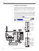
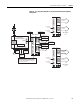
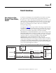
Figure 20 - Typical Gate Amplifier Interface to Multiple S6Rs
REV
GATES
REV
GATES
FWD
GATES
48V Ext P/S
(If Required)
To Stop
Circuitry
P/S
MONITOR
RELAY
GATE COUPLER
ASSEMBLY
GATE COUPLER
ASSEMBLY
GATE COUPLER
ASSEMBLY
GATE COUPLER
ASSEMBLY
GATE COUPLER
ASSEMBLY
GATE COUPLER
ASSEMBLY
GATE COUPLER
ASSEMBLY
GATE COUPLER
ASSEMBLY
L1, L2, L3
AC
CT FDBK to PFDC SAR
AC
Input
From PFDC
Regulator
Motor Field
Motor
M
+DC and -DC
Power Module
Output
AC Input (From Above)
CTs on
L1 and L3
AC To
Reverse Bridges
(Below)
+DC and -DC
Power Module
Output
FWD
4
FWD
3
FWD
2
FWD
1
REV
4
REV
3
REV
2
REV
1
To Encoder or Resolver Feedback Port
Encoder or Resolver Feedback
+
-
SD3K
FWD IN
SD3K
REV IN
PFDC
Gate Input
FWD
REV
RDY
Ext. P/S
120VAC
Gate Amplifer
Load Share
Reactors
PowerFlex DC
Stand-alone Regulator
KPT11
(15 Pin D-Shell)
Field Supply
40 A or 70 A
(2 Quad)
To Motor
Field
Gate Cable
Normally
Open Contacts
to Stop Circuitry
C1 D1 D C W V U 1A1 A1 1A2 A2 1 2 3 4 5 6 7 8
KPT31KAKP
Power Module
AC / DC
Feedback
Power Module
Armature Voltage
Feedback
Power Module
Thermostat and
CT Feedback
V1 U1
All Terminals are located
on the bottom of the unit.
See Parallel Power Modules and Load Share Reactors on page 65 for more information.