
Owner's manual

Rockwell Automation Publication 23P-UM001D-EN-P - July 2012 47
Gate Amplifier Installation and Wiring Chapter 3
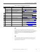
Table 10 - Recommended Welding Cable for High Frequency Grounding/Bonding
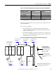
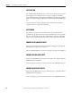
DC Drive High Frequency Grounding of Adjacent Cabinet Panels
Unless there is good continuity from panel to panel, the potential between the
panels will be different.
Notes on cabinet grounding:
• This grounding scheme is for high frequency grounding only. The
customer is responsible for all safety grounds and meeting local and state
equipment grounding codes.
• If the DC Drive Regulator components are mounted to a sub-panel, then
there must be a 1/0 Welding cable ground jumper between the sub-panel
and the main cabinet control panel.
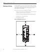
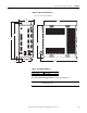
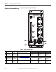
Figure 18 - DC Drive High Frequency Grounding / Bonding Configuration
Drive System Nominal
Motor FLA Per Section
Recommended Welding
Cable Size Cable Type
100…3000 Amps 2/0 Anixter #5J-2021 or Equivalent
3001…5000 Amps 3/0 Anixter #5J-3031 or Equivalent
5001…9000 Amps 250 MCM Anixter #5J-2501 or Equivalent
9001…20000 Amps 500 MCM Anixter #5J-5001 or Equivalent
Power
Transformer
Drive
Cabinet
Drive
Cabinet
Power
Entry
Bay
Gnd
Drive
Cabinet
M
Drive
Cabinet
Drive
Cabinet
M
Internal Bay to Bay
Grounding Cable Detail:
#1/0 kcmil compression lug
Burdy - YA25L6 or equal
Stud size = 1/2 inch
(both ends of jumper)
#1/0 kcmil welding cable
anixter #5J1011 or equal
Length determined in the field
to suit need
Internal “Bay to Bay”
1/0 Ground Cable
(see detail at right)
One Welding Cable,
Fine Strand.
See Table 10
for
Recommended Size.
Ground to Frame of Transformer. Ensure that
all Paint is Removed Before Attaching Lugs,
or “CAD Weld” Wire to the Frame.
One Welding Cable,
Fine Strand.
See Table 10
for
Recommended Size.
One Welding Cable,
Fine Strand.
See Table 10 for
Recommended Size.
One Welding Cable,
Fine Strand.
See Table 10
for
Recommended Size.
One Welding Cable,
Fine Strand.
See Table 10
for
Recommended Size.