
Owner's manual


Rockwell Automation Publication 23P-UM001D-EN-P - July 2012 35
Stand Alone Regulator Installation, Wiring and Configuration Chapter 2
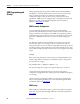
Example 3:
The only difference between Example 2 and Example 3 is the value of the burden
resistor. In this example the burden resistor is chosen as Rb = 5.0 Ohms.
In this example a standard CT ratio is chosen and the ratio no longer exceeds the
recommended CT ratio based on the gain calculation. This is due to the change
of the burden resistor from 2.5 Ohms to 5.0 Ohms.
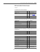
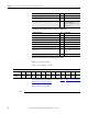
CT, Burden Resistor and Gain Calculation
Minimum CT Primary based on IOC trip point of 2.5 x Power Module rating
Maximum CT ratio based on Gain Range of Scaling Op-Amp in the Current
Feedback circuit
Input Values Units Description
IdN_pm_rtg: = 226 Amp Power module rating
Rb: = 5.0 Ohms Jumper J5 in the “On” position
and jumper J4 in the “Off”
position. See Figure 13 on
page 39 for jumper locations.
CT_pri: = 2000 Amp
CT_sec: = 1 Amp
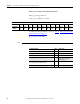
Value/Calculation Units Description
IOC_mult: = 2.5
CT_pri_min: =
IOC_mult x IdN_pm_rtg x 0.85
0.85 is the ratio of AC to DC
current
CT_pri_min = 480 Amp Based on IOC trip point
CT_ratio_min_based_on_ioc: = CT_pri_min / CT_sec
CT_ratio_min_based_on_ioc = 480 Based on IOC trip point
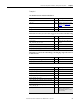
Value/Calculation Units Description
CT_ratio_max: = 1.2 x (IdN_rtg x Rb) / 0.612
CT_ratio_max = 2.216 x 10
3
Based on Gain <= 1.2
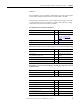
Value/Calculation Units Description
Vf_at_IdN_pm_rtg = 0.612 Volts Fixed Value
CT_ratio: = CT_pri / CT_sec
CT_ratio = 2 x 10
3
Ib_at_IdN_pm_rtg: = IdN_pm_rtg / CT_ratio
Ib_at_IdN_pm_rtg = 0.113 Amps
Vb_at_IdN_pm_rtg: = (IdN_pm_rtg / CT_ratio) x Rb