
Owner's manual

Rockwell Automation Publication 23P-UM001D-EN-P - July 2012 25
Stand Alone Regulator Installation, Wiring and Configuration Chapter 2
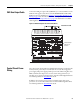
SAR Gate Output Cable
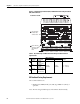
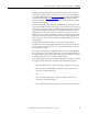
Connect the SAR gate output cable (23PAMP-Cx) to connector KPT11 on the
SAR unit. The opposite end connects to the POWERFLEX DC SAR GATE
INPUT on the Gate Amplifier. See Chapter 3
Gate Amplifier Installation and
Wiring on page 41 for more information on Gate Amplifier installation and
connections. See Cable Specifications
on page 78 for information on available
cable lengths for the 23PAMP-Cx cable.
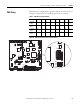
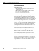
Figure 9 - SAR Gate Output Cable Connection (KPT11)
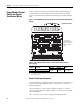
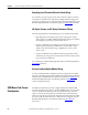
Control Circuit Power
Wiring
The control circuit for the SAR (not identified in the drawings contained in this
manual) must be powered by an external 230V AC or 115V AC, single phase
power supply. This power supply provides power for the SAR cooling fans and a
HIM, communication adapter, I/O, encoder, or DC analog tachometer (if
installed). See “Control Circuit Input Power” in the PowerFlex Digital DC Drive
User Manual, publication 20P-UM001
for details.
In addition, the control circuit power input terminals require short circuit
protection. See “Control Power Protection” in the PowerFlex Digital DC Drive
User Manual, publication 20P-UM001
for details.
1A1
(C)
A1 1A2
(D)
A2
1 2 3 4 5 6 7 8
V1 U1 C1 D1
D C W V U
KPT21 KPT11
KPT31
PE
SAR Gate Output
Cable (KPT11)
Connector
Bottom View of SAR