
Owner's manual

Rockwell Automation Publication 23P-UM001D-EN-P - July 2012 19
Stand Alone Regulator Installation, Wiring and Configuration Chapter 2
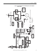
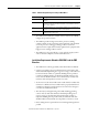
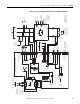
Figure 4 - Typical Stand Alone Regulator Interface to S6R Power Module
Pwr Mod / Arm Fdbk
Conn “KA”
2
1
3
4
5
6
7
8
Pwr Mod Thermal / CT Feedback
Conn “KPT31”
U
(L1)
U VW
MM
M
Internal Fuses
From AC Line Above
To SAR
Conn “KP”
Fault
To SAR
Conn “KPT31”
Warning
To Digital I/O
(if available)
Field Regulator (2 Quad)
U V
To Field Power
Module
Transformer
Incoming AC Line
From Incoming AC Line
Transformer
(External to SAR)
Field PM Therm
OT
+15 V ISO
+
-
Motor Field
Motor Field
Supplied by SAR
Field Power Module
(or separately excited)
U1 V1
C1
D1
Ext.
Rb
XCT
J4
J5
Armature
Current
Feedback
Gate Input
Gates
Gate Output
Conn “KPT11”
To Gate Amplifier
(refer to gate wiring
diagrams)
Stand Alone Regulator (SAR)
* Note: Armature Voltage
Feedback. Jumpers
must always be in place.
From Gate
Amplifier Output
(refer to gate
wiring diagrams)
Armature
Voltage
Feedback
See page 21 for
Fuse Sizes
(External to SAR)
Motor Arm Fdbk “-” A2
(PM Out - “D”) 1A2
Motor Arm Fdbk “+” A1
(PM Out + “C”) 1A1
AC / DC Feedback
Conn “KP”
D, “-”
C, “+”
W, AC_In
V, AC_In
U, AC_In
CT2 -
CT2 +
CT1 -
CT1 +
(Not_Used)
Therm_Com
ISO_Com
+V_Therm, +15V
0V ISO
#S2
(Test
Pt.)
2.5
Ohms
2.5
Ohms
Therm
Fault
On Pwr Mod
V
(L2)
W
(L3)
U, (L1)
V, (L2)
W, (L3)
CT1
CT2
U
(L1)
V
(L2)
W
(L3)
“+”
C
“-”
D
5A, 700V
5A, 700V
*(See
Note)
*(See
Note)
To Voltage
Feedback
Circuits