
Owner's manual

18 Rockwell Automation Publication 23P-UM001D-EN-P - July 2012
Chapter 2 Stand Alone Regulator Installation, Wiring and Configuration
Terminal/Signal and Wiring
Diagrams
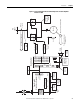
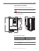
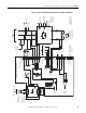
Use the diagram in Figure 3 - Stand Alone Regulator Terminal/Signal Block
Diagram as a guide for the general location of and connection signals for the main
input/output terminal blocks on the SAR. The diagram in Figure 4 on page 19
represents the recommended wiring for a typical SAR interface to a S6R power
module.
Figure 3 - Stand Alone Regulator Terminal/Signal Block Diagram
D, “-”
C, “+ ”
W, AC_In
AC / DC Feedback
V 1, AC_In
U1, AC_In
C1, DC_Out “+”
Field Bridge, AC Input / DC Ouput
PE (GND)
12345
Power Module Thermal / CT Feedback
Connector
“KP”
Connector
“KPT31”
678
+V _therm, +15V
Therm_Com
IS O_Com
(Not_Used)
CT1 +
CT1 -
CT2 +
CT2 -
Gate Output
Connector
“KPT11”
1A1 A1 1A2
Power Module Armature Feedback
Connector
“KA”
(P M Out + “C ”)
A2
Motor Arm F dbk “+ ”
(PM O ut - “D ”)
Motor Arm F dbk “-”
V , A C _In
U, AC_In
D1, DC_Out “-”
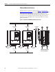
Bottom View
Front of Unit