
Owner manual


Publication 2364P-5.01 December 1999
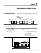
Catalog Numbers and Spare Parts Kits B-3
Control Power Source
Door-Mounted Pilot Lights
Metering
Protection
Unit Door Nameplates
Miscellaneous
Communication Options
Human Interface Module
Door-Mounted Pushbutton
Options:
Available on 2364P
Configuration Type(s):
x
x
x
x
x
x
x
x
x
x
x
x
x
x
x
x
x
x
x
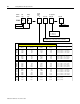
(1) NRU + (1) RGU
(1) NRU + (2) RGUs
(2) RGUs
(3) RGUs
or or
x
x
x
x
x
x
x
x
x
x
x
x
x
x
x
x
x
x
x
x
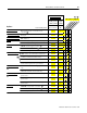
This option is applied:
6P
= Standard capacity control transformer for
control bus
4EA
= Unit-Not-Faulted / Control Bus Power On
Pilot Light
710P
= Analog AC input ammeter (L1 Phase only)
715P
= Analog DC bus voltage meter
14LSP
= Line RC suppressor module
M3EW
= White background with black lettering;
phenolic label
N3EB
= Black background with white lettering;
phenolic label
N3ER
= Red background with white lettering;
phenolic label
14WLBL
= Brady Datab ™ wire labels
J12
= 115V DC, 15A duplex receptacle
J11
= Audio phone jack
14G1
= Remote I/O communication interface board
14G2
= RS232/422/483 (using DF1 protocol)
and DH485 communication interface board
14G5
= DeviceNet communication interface board
14HAPC
= Door-mounted HIM (programmer
only)
14HNBC
= Door-mounted SCANport connector
(HIM cradle & internal connection cable only)
1R
= Fault Reset
88GF
= Ground-fault detection
14AFL
= Cooling fan air-flow-loss switch
14CN1
= ControlNet communication interface
module (mounted separate from power structure)
O
n
c
e
p
er
c
o
nf
i
g
ur
a
t
i
o
n
O
n
c
e
p
er
e
a
ch
u
nit
Onc
e
per ea
c
h RGU
Onc
e
p
er
ea
ch
N
R
U
x
x
x
x
x
x
x
x
x
x
x
x
x
x
x
x
x
x
x
x
2
3
4
5
5
6
7
8
Current Rating Codes: Rx, Sx, Tx, Vx Wx
9 10