
Owner manual

Publication 2364P-5.01 December 1999
Installation 15-11
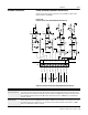
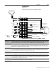
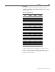
Customer Connections Analog Input/Output (RGU Main Control Board)
Analog input and output connections are available on TB1 of the
main control board (RGU).
Figure 15.10
Customer Connections–TB1 (RGU Main Control Board)
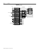
Table 15.A: Customer Connections–TB1 (RGU Main Control Board)
20k
0.047uf 0.047uf
20k
AGND
20k20k
20k20k
- +
AGND
1k
1k
TP27
.1
AGND
- +
1k
AGND
20k
0.047uf 0.047uf
20k
AGND
20k20k
20k20k
- +
AGND
1k
1k
TP28
.1
AGND
- +
1k
AGND
10
2200pf
10
AGND
100
AGND
TP30
-15V
+15V
+ -
.1
8.25k
+ -
10k
AGND
4700pf
10k
10k
AGND
560pf
10
2200pf
10
AGND
100
AGND
TP31
+ -
.1
8.25k
+ -
10k
AGND
4700pf
10k
10k
AGND
-15V
+15V
560pf
TB1
12345678910
Analog In 1 (-)
Analog In 1 (+)
Analog In 1 (Cmn)
Analog In 2 (-)
Analog In 2 (+)
Analog In 2 (Cmn)
Analog Out 1
Analog Out 1 (Cmn)
Analog Out 2
Analog Out 2 (Cmn)
-10V to +10V -10V to +10V -10V to +10V -10V to +10V
Terminals Description
TB1-1, TB1-2, TB1-3
TB1-4, TB1-5, TB1-6
Terminals TB1-1, 2, 3 are designated to Analog Input 1 and TB1-4, 5, 6 are designated to Analog Input 2. These can be
connected to a customer device which sends signals between ±10V. The analog voltage supplied is sampled by a 14-bit
analog-to-digital converter, and the resulting value is stored in parameter P36 (A/D Converter 0 Input). The internal circuitry
has an 80k differential input resistance and a 40k common-mode input resistance. 14AWG wiring is recommended for
customer connection.
TB1-7, TB1-8
TB1-9, TB1-10
Terminals TB1-7 and TB1-8 supply analog output from parameter P47 (D/A Converter 1 Output); TB1-9 and TB1-10 supply
analog output from parameter P48 (D/A Converter 2 Output). The RGU can be programmed to report parameter values (such
as trend parameters) to the customer device. The customer device must have a minimum 1k load resistance. 14AWG
wiring is recommended for customer connection.